28
User Manual
MN032006EN
Effective December 2017
415U Condor-long-range
wireless I/O and gateway
EATON
www.eaton.com
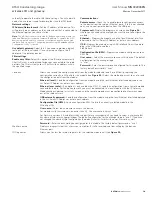
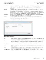
Figure 44. IO edit (analog inputs)
You can configure the following parameters for 415U-2 analog inputs.
Name
Enter a name for the analog input or leave the default name. The name can be up to 30 characters,
including spaces.
Filter Time (sec)
Period of time (in seconds) needed by the analog input to settle on a step change of an analog value.
By default, all inputs except the pulse rates have a time constant of five seconds. Pulsed input rates are
not filtered.
Scaling
You can scale analog inputs to suit data requirements of other systems. When sending analog inputs
to outputs on other 915U-2/415U-2 devices, select Default. Other scaling options provide support for
systems that need data ranges of 8-bit, 12-bit, and 16-bit (signed and unsigned). Use the Custom setting
to configure other scalings for systems that cannot be accommodated with any of the other options.
The graph shows how the scaling affects the relationship between the measured value (Engineering
Value) and the corresponding scaled 16-bit Register Value.
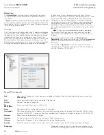
Lower and Upper
Set Points
These set points are the upper and lower control point values that will be used to turn on and off the
analog set point digital signals located at register 10009–10020.
Note
: Set point values are entered in the scale of the input. For example, analog input 1–4 should be
in mA, analog inputs 9–12 should be volts, and so on.
To control the set points, use the Invert and Window control options described below. All set points have
these controlling options.
Invert
Selecting this option inverts the set point control logic. The function does not change—only the operation
is inverted. For example, if the set point is “on” in its normal state, inverting the signal causes the set
point to be “off” in the normal state. By default, the checkbox is cleared and the set point logic is not
inverted.
Window
Selecting this checkbox sets the set point operation to Window mode. Clearing this checkbox sets the
set point operation to default mode.
Window mode
—In this mode, if the analog value is inside the upper and lower set points, the set point
will be active (on, “1”), and if the analog value is outside of these set points, the set point will be reset
(off, “0”).
Default mode
—In this mode, the set point operates in default mode. If the analog input is greater than
the upper set point, the set point status is active (on, or “1”). When the analog input is less than the
lower set point, the set point is reset (off, or “0”). When the analog value is between the upper and
lower set points, the previous value is maintained.
Note
: The upper set point must always be higher than the lower set point.

