21
User Manual
MN032006EN
Effective December 2017
415U Condor-long-range
wireless I/O and gateway
EATON
www.eaton.com
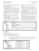
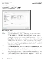
via the Ethernet connection on the device. To display the current
mappings for a module, open the module in the project tree and
click Mappings (see
Figure 34
).
Mappings are sent on the following triggers:
•
Change of state (COS)
—This method monitors the state of the
input that is being mapped. When the state changes, it triggers a
transmission. This is the primary method of sending input values
to a destination. As soon as the input change occurs the value
is immediately sent to the destination. Digital mappings are
triggered when the input changes from on to off, or from off to
on. Analog mappings are triggered when the input changes by a
predefined value, referred to as “sensitivity.” The sensitivity value
is set by configuring a sensitivity block for the particular input or a
range of inputs. See “Sensitivity blocks” on
page 32
for more
information.
•
Updates
—This method sends a message at a pre-configured
time regardless of the input value or state. For details, see
the Update Time field described in “Adding or editing mapping
parameters” on
page 22
.
•
Mapping force
—This method makes use of the Force Mapping
Transmit Register configuration on the Advanced page. It allows
a mapping to be triggered when a separate register is written
to a non-zero value. The register is written back to zero once the
mapping has triggered.
There are three types of mappings—write, gather scatter, and
read. Each type has advantages and disadvantages. The appropriate
mapping to use will depend on the data and requirements of
the system.
•
Write mapping
—A write mapping allows multiple sequential
values to be sent in one message. If you are mapping analog
values, the maximum I/O count is 64. However, if you are
mapping digitals it can be as many as 1024 because the digitals
values are packed into 16-bit words for transmission. The mapping
is sent on a change-of-state of any of the values being monitored,
and also on an update period.
•
Gather scatter mapping
—A gather scatter mapping is essentially
the same as write mapping, but instead of sequential register it
allows different I/O types to be sent in a single message. All I/O
types, including digital, analog, long (32-bit registers) and floating
point values, can be sent in a single message. A gather scatter
mapping has a maximum I/O count of 32 values of any data type
(digital, analog, longs, or floats).
•
Read mapping
—Read mappings are similar to write mappings
in that they allow multiple sequential values to be sent. However,
instead of writing the values to another module, the data is
requested from the remote module, which responds with the
requested data. This type of mapping is suited to a polling
system where the receiving station initiates when it wants to
communicate, for example, by sending a read request when it
requires the information or by sending a request on a timed basis.
Figure 34. Mappings
WIB configuration options
The following options are available on the “Advanced” tab of
the Mappings screen (see
Figure 42
) allow you to fine-tune the
operation of the WIB protocol. The default values are appropriate for
almost all systems and should not need to be changed.
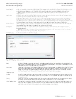
Tx Ack Count
Total number of attempts to be made to transmit a mapping with its Acknowledge checkbox selected if no
acknowledgment message is received. In most cases, the default value of three transmissions is recommended.
Tx Ack Timeout
Time to wait before deeming a mapping message as “unacknowledged” if the Acknowledge checkbox is selected in
the mapping. The default value is two seconds.
Tx Un Ack Count
Number of times to send an IO mapping if the Acknowledge checkbox is cleared in the mapping.
Figure 35. WIB Protocol configuration


