6
7
INM MTL9373-FB3 Rev 1
INM MTL9373-FB3 Rev 1
4.1 Mounting overview
Before mounting an enclosure, be aware of and check the following points.
a) The enclosure is designed for mounting on a vertical surface, with the cable
entry at the lowest point, as shown in the upper part of Figures 4.1. and 4.2.
The permitted ambient temperature range in this orientation (–20°C to
+60°C), external to the enclosure, must not be exceeded. Avoid radiant heat
by locating the enclosure away from direct sunlight or local sources of heat.
b) The enclosure has an ingress protection rating of IP65/IP66 (to EN60529). The
mounting location should be chosen to comply with the rating of the
enclosure and ensure that this rating is not compromised.
c) Adequate security should be provided against unauthorised interference.
d) All the necessary gland holes have been prepared in the enclosure. One has a
breather fitted and the others are fitted with appropriate blanking plugs.
e) Wherever a blanking plug is replaced by a cable gland, the gland fitted must
be Ex e certified and have an ingress protection (IP) rating that maintains the
overall rating of the enclosure.
f) Enclosure blanking plugs that are factory fitted are tightened lightly for ease
of removal, and so any blanking plugs that are not removed must be tightened
to the required torque, before operation, to meet the IP rating.
g) All cable gland holes must contain either a suitable cable gland or a
blanking plug.
WARNING!
It is not permitted to create additional holes in the enclosure as
this would violate the certification.
4.2 Preparation
a) Remove any temporary protection or packing materials.
b) The enclosure can be mounted on any suitable structure using the enclosure’s
integral mounting brackets.
c) The fixing bolts must be suitable for the mounting surface and the
environmental conditions.
d) Prepare holes in the mounting surface, on the centres shown in Figure 4.1 or
4.2 to accept suitable screws/bolts for mounting.
e) It is advisable before mounting, to do any necessary replacement of the cable
entry blanking plugs with a suitable gland. For further details see Section 4.1
e) and f).
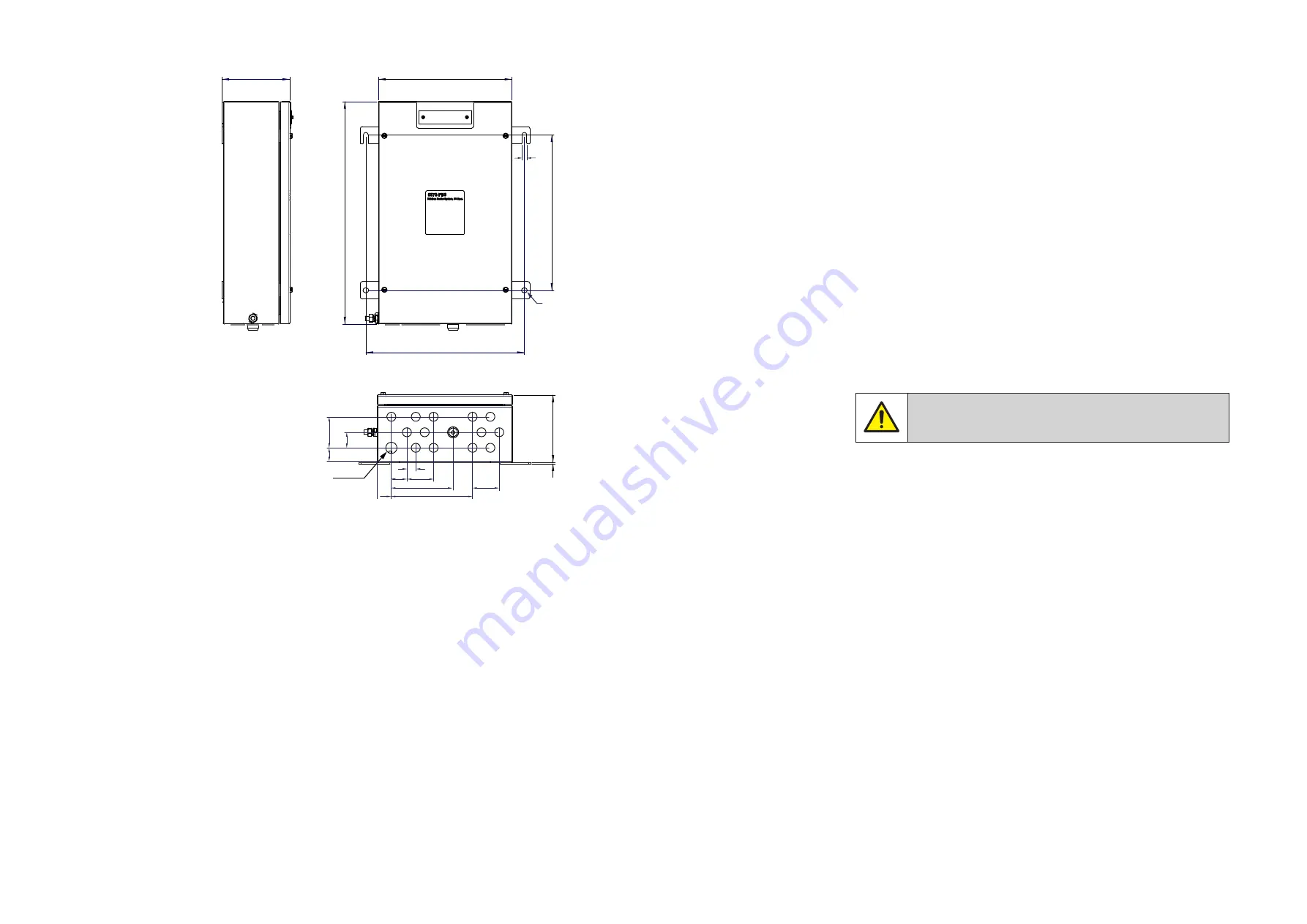
Figure 4.2 –
Fieldbus Barrier Standard Large enclosure dimensions
Notes:
1. This drawing shows the enclosure lid fitted with a stainless-steel mounting
bracket and a traffolyte tag label. This bracket is an option available when
ordering and is not a default feature.
2. A hinged lid (LHS) with a quarter-turn lock (not shown here) is a further option
when ordering. This does not affect the overall enclosure dimensions.
152
Trunk in
3
362
354
305
508
155
30
35
70
3x20=60
20
32
35
142
183
3x20=
60
11
Ø 11


