background image

20

21

INM MTL9373-FB3 Rev 1

INM MTL9373-FB3 Rev 1

6.3  Trunk connections 


Note the warning given on the covers protecting all of the trunk wiring areas. 

WARNING! 

Do not remove or replace while circuit is live if a flammable or 

combustible atmosphere is present

 
Work on the trunk wiring, protected by additional covers, requires the trunk power to 
the enclosure to be isolated, or a gas clearance certificate obtained. 

Once the conditions are known to be safe, the necessary plastic cover(s) over the 
Trunk wiring may be removed. Refer to Sections 5.4 or 5.5 for additional information 
about the relevant trunk wiring connections. 

When any changes or checks have been carried out, ensure there are no loose 
implements left before replacing protective cover for the trunk wiring. Replace the 
transparent protective cover over the trunk wiring and ensure that there is positive 
engagement of the retaining clip.

6.4  Removal and replacement of a module 

If it is found necessary to swap-out a complete barrier module in the enclosure, 
proceed as below. 

WARNING! 

The following procedure requires the power to the barrier/enclosure to 

be isolated. No work is permitted unless the power has been isolated 

or the environment is known to be non-hazardous.

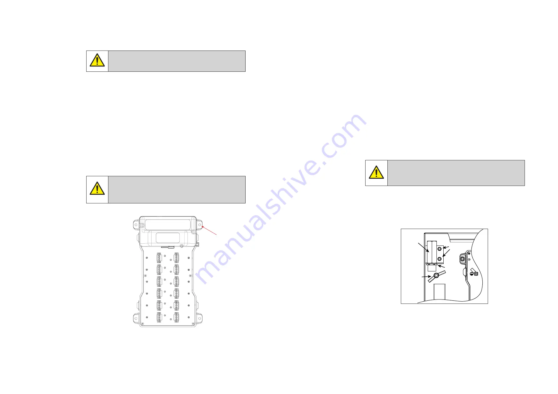
Figure 6.1

 – Removing a barrier module 

Use the following procedure and reference to Section 5.3.1 may help.


a)  Unclip and remove the Trunk Terminal cover


b)  Loosen the two screws securing the pluggable, TRUNK-IN wiring connector  


  and unplug it. Do the same for a TRUNK-OUT connector if there is a cable  


  connected. Arrange these safely to the side of the barrier.


c)  In turn, loosen the two screws securing each pluggable, spur-wiring connector  


  and unplug the connectors. Arrange the connector wiring so that you have  


  access to the barrier fixings.


d)  The barrier is secured to the backplane of the enclosure by four M5 flange  


  nuts. (See Figure 6.1 for their locations.) Loosen these in turn and remove  


  them to free the barrier and remove it from the enclosure.


e)  Replacement is the reverse of the removal process – tightening barrier fixing  


  nuts to a recommended torque of 2.5 Nm and connector screws to  


  0.5 - 0.6 Nm. 

 
Follow site practice on the reuse of any locking washers; replacement may  
be advisable.

6.5  Replacement of a TP-32 Surge Suppressor 

WARNING! 

The following procedure requires the power to the barrier/enclosure to be 

isolated. No work is permitted unless the power has been isolated or the 

environment is known to be non-hazardous. 

Replacement of this item will depend upon the enclosure type for wiring details. 
Refer to sections 5.4 or 5.5 for information on the wiring of the enclosure type.

The TP-32 has a threaded section on its body with a retaining nut to enable it 
to be fitted to a mounting bracket on the inside of the enclosure. Removal and 
replacement will be simplified by removing the item complete with its mounting 
bracket.

Figure 6.2

 – TP-32 mounting details

Barrier

mounting

locations

x 4

TP-32

M6 (x2)

Grounding

stud

Retaining

nut

Summary of Contents for Crouse-Hinds 9373-FB3 Series

Page 1: ...9373 FB3 MTL Compact Fieldbus Barrier System June 2020 INM MTL9373 FB3 Rev 1 Instruction manual MTL fieldbus networks ...

Page 2: ... 15 5 5 3 Trunk Termination 16 5 6 Spur wiring connections 17 5 6 1 Connecting the spur cables 17 5 6 2 Fitting FS32 Spur Surge modules 17 5 7 Final checks 18 6 MAINTENANCE 19 6 1 General 19 6 2 Spur connections 19 6 2 1 Removing a Spur Surge module 19 6 2 2 Adding a Spur Surge module 19 6 3 Trunk connections 20 6 4 Removal and replacement of a module 20 21 6 5 Replacement of a TP 32 Surge Suppres...

Page 3: ...are fully understood by the personnel responsible Observe national and local installation and mounting regulations e g IEC 60079 14 WARNING These assemblies may not be used in explosion hazard area applications if they have been used previously in general electrical installations During operation Make the relevant instructions available at all times to the operating personnel Observe safety instru...

Page 4: ...dbus instruments in IIC Zone 0 hazardous areas The spur connections are compatible with both FISCO and Entity certified field instruments The fieldbus barrier is mounted in a 316L stainless steel increased safety Ex e enclosure that segregates spur and trunk cabling in accordance with hazardous area certification Inside the enclosure the incoming trunk wiring terminates in a separate compartment c...

Page 5: ...afe Intrinsically safe spurs 1 2 3 10 11 12 Intrinsically safe spurs T 1 2 3 10 11 12 from HOST Trunk Not intrinsically safe Intrinsically safe spurs 1 2 3 10 11 12 Intrinsically safe spurs T a b c 4 MECHANICAL INSTALLATION See Figure 4 1 and 4 2 below for the dimensions fixing locations and cable gland positions of the two main enclosure options Figure 4 1 Fieldbus Barrier Standard Small enclosur...

Page 6: ...for ease of removal and so any blanking plugs that are not removed must be tightened to the required torque before operation to meet the IP rating g All cable gland holes must contain either a suitable cable gland or a blanking plug WARNING It is not permitted to create additional holes in the enclosure as this would violate the certification 4 2 Preparation a Remove any temporary protection or pa...

Page 7: ...nnection is isolated from any source of power CAUTION The temperature inside the enclosure could rise to 60 C Ensure that all cables and cable glands fitted are rated to withstand these temperatures 5 1 Overview The barrier module receives power from the incoming trunk cable and requires no further source of power The equipment shall be powered only from supplies conforming to IEC 61158 2 Type A f...

Page 8: ... A B Local ground A B Host ground Trunk shield Spur shields 5 3 Trunk cable wiring The 9373 FB3 PX SS product has a range of user options for trunk wiring These range from a single trunk cable entry allowance for an onward link to a second enclosure as shown in Section 3 and the ability to manage and marshal multiple spare trunk pairs if required In addition the option for surge protection on the ...

Page 9: ...ur wiring 3 Ensure also that there is sufficient length of cable inside the enclosure to allow for bends etc and without causing any strain Connect the prepared ends of the incoming fieldbus trunk cable into the and S terminals of the TRUNK IN connector see Figure 5 6 observing colour coding in accordance with site wiring regulation Figure 5 6 Fieldbus Barrier Trunk wiring If there is no surge sup...

Page 10: ...he trunk cable entering the enclosure has no spare wires requiring management ignore this section and move on to Section 5 5 3 The Standard Large enclosure may be ordered with additional terminals to manage multi core cables where only one cable pair is used for the active trunk circuit These spare pairs may require only to be managed in a convenient way or they may be an element of the system des...

Page 11: ...ctor supplied on the carrier and remove it from its socket b Insert the FS32 module into the now vacant socket on the carrier tighten the two side securing screws and the central protective ground screw to a recommended torque of 0 5 0 6 Nm c Fit the connector removed at Step 1 above into the socket on the FS32 and tighten its two securing screws also to a recommended torque of 0 5 0 6 Nm Removal ...

Page 12: ...S32 Spur Surge Protection modules All other wiring to the barrier requires the trunk power to be isolated or a gas clearance certificate to be obtained before any work is carried out 6 2 Spur connections All of the spur connections are intrinsically safe and therefore may be live worked in a hazardous area without gas clearance while complying with normal permit to work procedures If spur wiring i...

Page 13: ...b Loosen the two screws securing the pluggable TRUNK IN wiring connector and unplug it Do the same for a TRUNK OUT connector if there is a cable connected Arrange these safely to the side of the barrier c In turn loosen the two screws securing each pluggable spur wiring connector and unplug the connectors Arrange the connector wiring so that you have access to the barrier fixings d The barrier is ...

Page 14: ...hat theTerminator link is in the correct position Replace the transparent protective cover over the terminal block and ensure that there is positive engagement of the retaining clip 6 6 Regular Maintenance checks Check the general condition of the installation occasionally to ensure that no deterioration has occurred At least every two years and more frequently for harsh dusty or dirty environment...

Page 15: ...esher training shall be given on a regular basis See clause 4 2 of EN 60079 17 b The apparatus has been designed and manufactured so as to provide protection against all the relevant additional hazards referred to in Annex II of the Directive such as those in clause 1 2 7 c This apparatus has been designed to meet the requirements of electrical apparatus in accordance with EN 60079 0 EN 60079 7 EN...

Page 16: ...y have specific requirements which should also be met c Maintenance of internal components while powered is limited to those actions permitted in Section 5 of this manual 8 5 Repair This product or any of its ancillary fittings cannot be repaired by the user and must be replaced with an equivalent certified product 8 6 Marking Each barrier is marked in compliance with the Directive and CE marked w...

Page 17: ...India No 36 Nehru Street Off Old Mahabalipuram Road Sholinganallur Chennai 600 119 India Tel 91 0 44 24501660 24501857 Fax 91 0 44 24501463 E mail mtlindiasales eaton com ITALY MTL Italia srl Via San Bovio 3 20090 Segrate Milano Italy Tel 39 02 959501 Fax 39 02 95950759 E mail chmninfo eaton com JAPAN Cooper Crouse Hinds Japan KK MT Building 3F 2 7 5 Shiba Daimon Minato ku Tokyo Japan 105 0012 Tel...

Reviews: