22
23
INM MTL9373-FB3 Rev 1
INM MTL9373-FB3 Rev 1
1) Disconnect the red (+), black (–) and yellow/green wires of the TP-32 module. The
+ and – will either be on the Fieldbus Barrier or on the DIN rail terminals,
depending upon the enclosure type. The yellow/green wire will be connected via a
ring terminal to the M6 grounding stud.
2) The bracket is held in place with two nuts on M6 studs. Loosen and remove these
nuts to detach the bracket from the enclosure.
3) Loosen and remove the retaining nut to free the TP-32 from its mounting bracket.
Fitting a replacement TP-32 is the reverse of the removal procedure. Torque the M6 nuts
to 4.5Nm (3.3lbft).
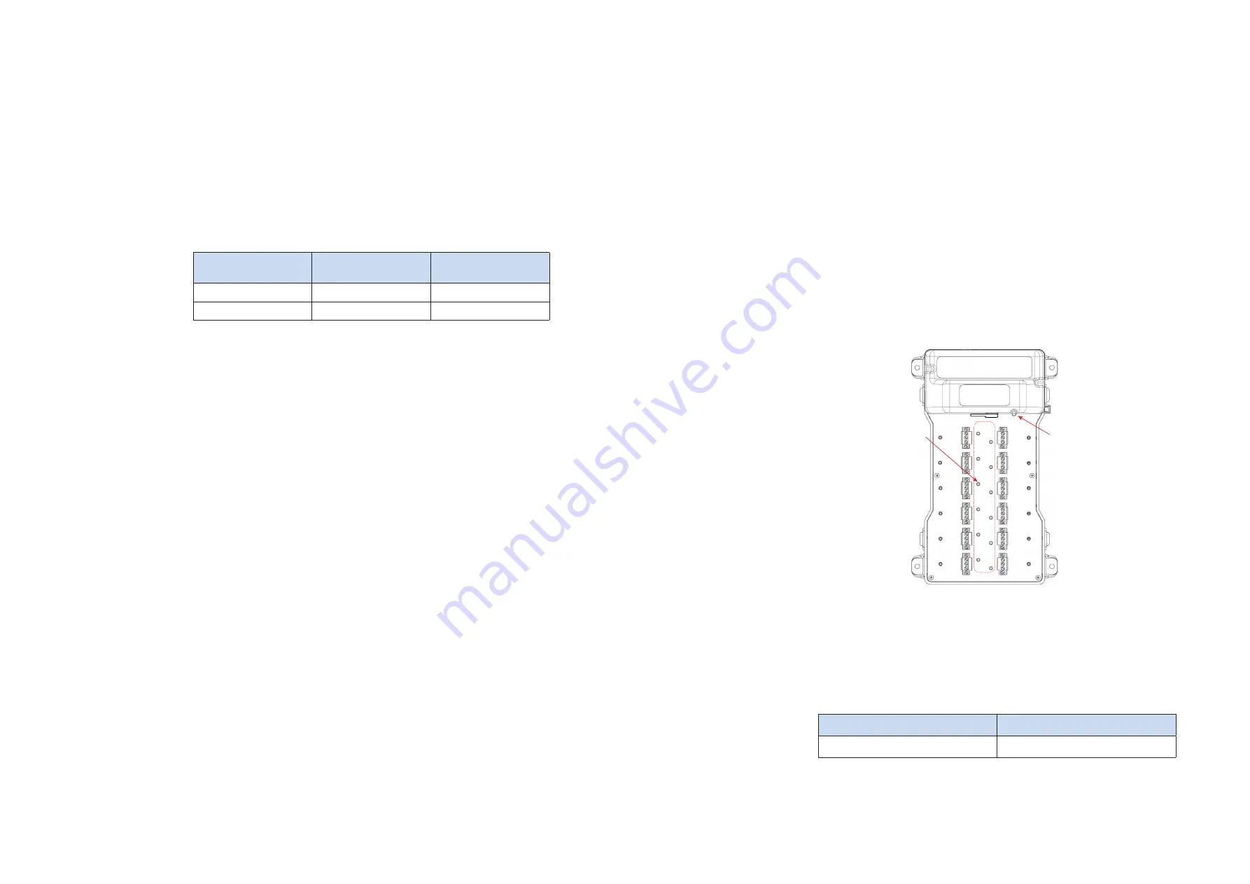
Connect the TP-32 wires in the same manner as before its removal – refer to Figures 5.4
and 5.7 and the table below for additional details.
TP-32 wires
TRUNK OUT
connector
Trunk In DIN rail
connector
Red
+
+
Black
-
-
The yellow and green stripe wire on the TP-32 should be connected to the protective
grounding stud located beside it. DO NOT connect this wire to the ‘S’ terminal of the
trunk connector.
Before refitting the Trunk wiring protective cover:
• Check all wiring connections
• Confirm that the Grounding link is in accordance with the Option required
• Check that the Terminator link is in the correct position
Replace the transparent protective cover over the terminal block and ensure that there is
positive engagement of the retaining clip.
6.6 Regular Maintenance checks
Check the general condition of the installation occasionally to ensure that no
deterioration has occurred. At least every two years (and more frequently for harsh,
dusty or dirty environments) check:
• Clean only with a moist cloth and detergent.
• the condition of all wire connections/terminations/screens
• that all of the fixing and cover screws and blanking plugs are secure and the
enclosure breather/drain is clear
• that there are no signs of damage or corrosion
• that the level of any accumulated dust on the barrier enclosure does not
exceed 5mm
In addition, take advantage of plant maintenance shutdown periods or whenever the
area is known to be non-hazardous, to check wiring quality by ensuring that the dc
voltage on the fieldbus trunk, when measured at the enclosure, is >16V. This can be
performed using a multimeter or an FBT-6 fieldbus tester.
7
TROUBLESHOOTING
Each Fieldbus Barrier module is fitted with LED indicators to assist the user with
fault identification.
Figure 7.1
–Barrier LED locations
Consult the following tables to understand the meaning of the LED states.
Power LED (Green)
ON
OFF
Trunk power applied
Insufficient or no trunk power
Power LED
Spur LEDs


