5
General Information
ControlKeeper 4
configuration. No T-Taps/Stars should be used. The GDS-I
device should reside somewhere within the daisy-chain
switch net work. Total daisy-chain network length should not
exceed 1000 feet.
The following instructions describe the GDS-I device
connection to the ControlKeeper 4. Please refer to the
Digital Switch Installation Instructions for information on
wiring the Digital Switch network to the GDS-I.
1. Mount the GDS-I next to the ControlKeeper 4 panel.
A six foot phone style cable has been provided for
connectionto the ControlKeeper 4 panel.
2. Run a length of the Digital Switch LC or Belden cabling
from the GDS-I location to the low voltage section of
the ControlKeeper 4.
3. Connect the RED wire in the cable to the +V terminal
on the back of the GDS-I and to the ControlKeeper 4 at
one of the switch input +24VDC terminals.
4. Connect the BLACK wire in the cable to the GND
terminal on the back of the GDS-I and to the
ControlKeeper 4 remote power connector GND
terminal.
5. Tape back or cap the blue and white wires and shield
wire for the cable. They will not be used for connection
between the GDS-I and lighting controller.
6. Locate the 6 foot phone style cable included in the
GDS-I box. Run this from the GDS-I into the low voltage
section of the ControlKeeper 4 enclosure plugging the
end with 9 pin head into the GDS-I. Plug the end the
RJ11 phone style plug into the ControlKeeper 4.
-
+
NETWORK
RS232
VDC
DC
GND
+24
CH4
OFF
ON +24
CH3
OFF
ON +24
CH2
OFF
ON +24
CH1
OFF
ON +24
RESET
NET TERM
U28
U25
U26
U22
U24
U1
9
U20
U29
TB7
4
1
2 3
5 6
8
7
J2
J1
U1
8
U27
U23
U21
TB5
TB4
S7
RN1
J3
C26
C20
U1
7
Cabling is Eaton’s Cooper LC Cable,
Belden 1502R, or Belden 1502P
Wire Phone Style Cable to
RJ11 Jack on CK4 and to GDS-I
GDS-I
BLACK Wire From GDS-I
GND to CK4 GND
RED Wire From GDS-I V
+ to CK4 +24VDC
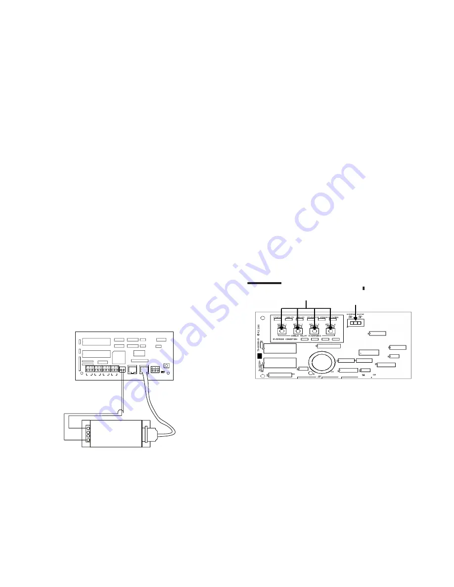
Figure 9. GDS-I Wiring Detail
Applying Power
1. After wiring is complete, make certain to clean panel
of all wire clippings and fragments ensuring that no
fragments get lodged between the circuit board and
enclosure.
2. Ensure that there are no loose wires or exposed wires
that could short out.
3. Make certain that the line voltage section of the
enclosure is closed and secure.
4. Power-up the unit. It is recommended that the unit be
cleared of all programming unless the unit has been
sent pre-programmed to you by the factory. To perform
this step, hold down the reset button for about
15 seconds.
5. Please refer to the operation section of this instruction
for information on turning ON and OFF lighting loads.
Refer to the Keeper Enterprise Software manual
for information regarding the programming of the
ControlKeeper 4 jumper.
Relay Override Operation
The ControlKeeper 4 has two means of override located
on the logic board: individual relay override buttons and a
hardware override switch. It is possible to control lighting
loads and override programming using these override
mechanisms.
Individual Relay
Override Switches
Hardware Override Switch
ControlKeeper® 4 Upper Left Corner
Figure 10. ControlKeeper 4 Status LEDs
Individual Relay Override Notes
Each relay on the ControlKeeper 4 may be overridden using
the individual relay override switches located at the top
left of the low voltage section. See Figure 9 for location
of these switches. These override switches will toggle the
associated relay’s state with each push of the button. This
type of over ride is temporary in that the override will last
until the next command that the relay is given.
Hardware Override Switch Notes
In addition to the individual relay override switches, there
is a hardware override switch that allows the override of
all relays on the board. If this switch is moved to the ALL
ON or ALL OFF position, all four relays will remain ON or
OFF as long as the switch is in that ALL ON or ALL OFF
position. The ON or OFF state is maintained regardless of
programmed state. In order for relays to run programmed


