4
Instruction Booklet
IL70C1080H03
Effective May 2014
Instructions for Field Installing Ground Fault Alarm/Power
Supply Modules into Digitrip 520M Equipped Eaton
Magnum and Magnum DS Circuit Breakers
EATON www.eaton.com
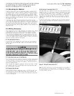
Figure 5. Components of the Trip Deck and Installation of the Digitrip Unit into a Magnum Breaker (Side View).
6.3 Removing the Trip Unit
To remove the trip unit from the circuit breaker, deflect the spring
clip underneath the trip unit with a screwdriver. When unlocked, you
will be able to pull the trip unit straight out and, by doing so, will dis-
engage the trip unit’s printed circuit board connectors K1 & K2 from
the circuit breaker. This action should be firm, but not forced (see
Figure 5).
6.4 Removing the Trip Deck Mounting Plate
Using the # 2 Phillips screwdriver, remove the two top screws that
anchor the steel trip deck plate into the mounting boss. Be careful
not to damage the Trip Indicator Assembly (and Over Current Trip
Switch / Bell Alarm if your breaker contains this option).
otee:
N
Observe how the Trip Indicator Assembly (Figures 5 & 6) tabs are
located BEHIND the steel mounting plate. Upon reassembly, the unit must
be reattached in an identical manner.
Next, loosen the two screws at the bottom of the steel mount-
ing plate. Lift the plate upward then swing it to the left to expose
the cavity where the Ground Alarm / Power Supply Module will be
mounted.
Figure 6. The Trip Indicator Assembly.
Trip Indicator Assembly
(Over Current Trip Switch / Bell Alarm)
Bell Alarm Trip Indicator
Guide Pin
Rating Plug
(3 Pins)
M-4x80 mm Screw
(Shown Disengaged)
Guide Pin
520 M Trip Unit
Spring Clip
Steel Mounting Plate
Mounting Boss
Frame
Ground Alarm
Power Supply Module
K1 Connector - Pin 1
M-4 Bushing
K2 Connector - Pin 1
Notee:
Locations of
J3 & J4 Connectors
Mounting Boss
Notee:
Trip Indicator Stabs Go
Behind the Steel Mounting Plate


