5
Instruction Booklet
IL70C1080H03
Effective May 2014
Instructions for Field Installing Ground Fault Alarm/Power
Supply Modules into Digitrip 520M Equipped Eaton
Magnum and Magnum DS Circuit Breakers
EATON www.eaton.com
7.0 Mounting the Module
Carefully remove any wire ties and move existing wiring to the left.
The module mounts directly under the steel plate so that the hole in
the module aligns with the 4 mm threaded insert. Hold the module
against the mounting surface to confirm correct positioning. Take
one of the supplied self tapping screws and partially screw it into the
bottom retaining boss for the module. The screw anchoring tabs for
the module are slotted.
Slide the bottom tab of the module behind the partially inserted
screw. Take the second screw and place it in the other slotted notch
on the top of the module and anchor the unit in place in the breaker.
Now go back and tighten the bottom retaining screw and ascertain
that the Ground Alarm / Power Supply Module is firmly seated in the
Magnum frame.
8.0 Wiring Harnesses
Two wiring harnesses must be attached to the Ground Alarm / Power
Supply Module. The first, a three conductor connector, is already
pre-wired into the breaker at the factory. The second is supplied
with the field installable upgrade kit. It comes ready to install with
a four conductor connector on one side and male pins on the other
which are inserted into the Secondary Block “A” which is a black con-
nector on the top left side of the breaker
8.1 Preparing the Harness
Using several of the supplied tie wraps, secure the four conductor
harness into a common bundle. Cleanly trim the excess tails from
the tie wraps.
CAUTION
IT IS IMPORTANT THAT THE TIE WRAPS ARE TRIMMED AND THAT THE
NEW HARNESSES AND EXISTING WIRING BE TUCKED NEATLY BACK INTO
THE BREAKER FRAME. LOOSE OR STRAY WIRES MIGHT INTERFERE WITH
PROPER FIT AND ALIGNMENT OF THE TRIP UNIT. ADDITIONALLY, THIS
SAME SITUATION MIGHT INHIBIT MOVEMENT OR OPERATION OF CERTAIN
MECHANICAL COMPONENTS WITHIN THE BREAKER.
8.2 Attaching Harnesses to the Module
Take the pre-wired, three conductor connector with the locking edge
facing up and push firmly into place on the three conductor pin set
(J3) on the left side of the top of the module. Confirm that the con-
nector is locked in place.
Next, take the four conductor connector and similarly attach it to the
four conductor pin set (J4) on the right side of the top of the mod-
ule. Confirm that it is secure.
8.3 Running the Harness
Rout the end of the four conductor harness with the four pins from
the Ground Alarm Power Supply Module between the bosses up
to the Secondary Block “A.” Be sure that the wires do not interfere
with any moving parts.
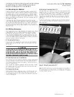
8.4 Wiring the Secondary Block “A”
The ends of the four conductor harness are to be connected to the
Secondary Block “A” on the top, left side of the breaker (see Figure
7). The wires are marked A-10, A-11, A-14, and A15. According to
the label on the block, insert them into the proper terminal slots.
This is done simply by pushing them in until they lock. After the
audible “click,” confirm that they are secure by slightly pulling on
each wire.
Tuck away and tie wrap all wiring neatly so that it will not interfere
with any mechanical operation or prevent improper fit of reassem-
bled components.
Figure 7. Wiring Secondary Block “A”.
otee:
N
The AMP
extraction tool is not actually required for the installation of
the Ground Alarm / Power Supply Module. It is needed only if the pins are
accidently inserted into the wrong locations in Secondary Block “A” and have
to be removed and reinserted.
Trip Indicator Assembly
(Over Current Trip Switch / Bell Alram)


