3. Installation
3.4 Mounting
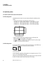
3.4.1.1 Preparations
1. Select the installation location you want for the device.
Make sure that all site criteria are met → page 42.
2. Make a cutout with the right size for the HMI at the location you selected.
3. Make sure that the mounting cutout has the right size.
4. Check that the gasket is resting properly inside the groove at the back of the
Widescreen terminal.
5. Pre-assemble the holding brackets with the set screws.
Screw the Internal hexagon M 4 x 25 DIN 914 galvanized set screws into the
holding brackets.
Fig. 12: Pre-installing the holding brackets
The holding brackets are included as accessories with the HMI. The number of
brackets will depend on the specific device model
8 x
10" devices
10 x
15" devices
12 x
21" devices
All holding brackets need to be installed in order to get an IP65 degree
of protection.
All holding brackets need to be installed for the UL listing.
Together with the gasket, the holding brackets are the main element
required for achieving an IP65 (at front) degree of protection.
The purpose of the holding brackets is to secure the Panel-PC, Terminal and
Terminal with Extender RX in the installation cutout, e.g., on the control panel door.
To this end, the brackets must be hooked into the enclosure and screwed against the
control panel door, etc.
50
XP-504
04/2022 MN048028EN Eaton.com
Summary of Contents for 199996
Page 1: ...Manual 04 2022 MN048028EN XP 504 Manual...
Page 4: ......
Page 86: ...5 Commissioning 5 2 Running the XP 504 86 XP 504 04 2022 MN048028EN Eaton com...
Page 98: ...7 Operating System 7 2 Windows 10 Enterprise LTSC 98 XP 504 04 2022 MN048028EN Eaton com...
Page 100: ...8 Faults 100 XP 504 04 2022 MN048028EN Eaton com...
Page 130: ...Appendix A 2 Further usage information 130 XP 504 04 2022 MN048028EN Eaton com...


