3. Installation
3.1 Prerequisites for the location of use
3.1.1 Installation position
The following must be taken into account when selecting the installation position:
l
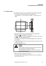
The size of the installation cutout depends on the device type:
easy-RTD-DC-43-...: e = 123 mm (4.84") ± 1 mm (0.04"), f = 87 mm (3.43") ± 1 mm
(0.04")
e
f
d
α
α
l
Make sure that the material at the installation location is sufficiently thick
Material thickness of 2 mm (0.08") ≦ d ≦ 5 mm (0.2")
and flatness of
≦ 0.5 mm (0.02") at the installation cutout with a surface rough-
ness
Rz ≦ 120; IP 65 → DIN ISO 2768-2 (K)
l
The controls and connectors must remain accessible even after the device has
been installed.
l
If no forced ventilation is being used, the device must not be mounted at an angle
exceeding α max. ± 90°.
l
No direct sunlight on the device.
CAUTION
UV LIGHT
Plastics will become brittle when exposed to UV light. This artificial
aging will reduce the easy-RTD unit's lifespan.
Protect the Resistive-Touch display unit from direct sunlight and
other sources of UV radiation.
l
Make sure that the easy-RTD does not overheat.
l
The minimum clearance to components that radiate heat, such as transformers
under heavy loads, is 15 cm.
easy Remote Touch display
06/21 MN048027EN Eaton.com
33
Summary of Contents for 199740
Page 1: ...Manual 06 21 MN048027EN easy Remote Touch display Manual ...
Page 4: ......
Page 8: ...8 easy Remote Touch display 06 21 MN048027EN Eaton com ...
Page 14: ...0 1 About this documentation 14 easy Remote Touch display 06 21 MN048027EN Eaton com ...
Page 24: ...1 Description 1 10 Marine approvals 24 easy Remote Touch display 06 21 MN048027EN Eaton com ...
Page 48: ...4 External connections 4 2 Ethernet 48 easy Remote Touch display 06 21 MN048027EN Eaton com ...
Page 78: ...8 Faults 78 easy Remote Touch display 06 21 MN048027EN Eaton com ...


