background image

Installation Plan and Unpacking

Eaton

® 

Power Xpert 9395 Integrated Battery Cabinet (Model 1085 and 1085HR) Installation Manual    164201687—Rev 06    

www.eaton.com/powerquality

3-9

3.3

Inspecting and Unpacking the Battery Cabinet

The battery cabinet is palleted separately for shipping. The cabinet is shipped bolted to a pallet consisting of 
four angle metal supports secured to two four-inch by six-inch wood supports, as shown in Figure 3-5 and 
protected with outer protective packaging material.

CAUTION

The battery cabinet is extremely heavy (see Table 3-1). If unpacking instructions are not closely 

followed, the cabinet may tip and cause serious injury.

1.

Carefully inspect the outer packaging for evidence of damage during transit.

CAUTION

Do not install a damaged cabinet. Report any damage to the carrier and contact your service 
representative immediately.

2.

Use a forklift or pallet jack to move the packaged cabinet to the installation site, or as close as possible, 
before unpacking. Insert the forklift or pallet jack's forks between the pallet supports on the bottom of the 
unit.

CAUTION

Do not tilt the UPS cabinet more than 10° from vertical or the cabinet may tip over.

3.

Set the pallet on a firm, level surface, allowing a minimum clearance of 3m (10 ft) on each side for 
removing the cabinet from the pallet.

4.

Remove the protective covering from the cabinet.

5.

Remove the packing material, and discard or recycle in a responsible manner.

6.

Inspect the contents for any evidence of physical damage, and compare each item with the Bill of Lading. 
If damage has occurred or shortages are evident, contact your service representative immediately to 
determine the extent of the damage and its impact upon further installation.

NOTE

For the following step, verify that the forklift or pallet jack is rated to handle the 
weight of the cabinet (see Table 3-1 for cabinet weight).

NOTE

The battery cabinet is shipped with a debris shield covering the ventilation grill on 

top of the unit. Do not remove the debris shield until installation is complete.

NOTE

While waiting for installation, protect the unpacked cabinet from moisture, dust, and 

other harmful contaminants. Failure to store and protect the UPS properly may void 
your warranty.

Summary of Contents for 1085

Page 1: ...Eaton Power Xpert 9395 Integrated Battery Cabinet Model 1085 and 1085HR Installation and Operation Manual ...

Page 2: ......

Page 3: ...Eaton Power Xpert 9395 Integrated Battery Cabinet Model 1085 and 1085HR Installation and Operation Manual ...

Page 4: ...NSTRUCTIONS Eaton Powerware LanSafe Powerware Hot Sync and X Slot are registered trademarks and ConnectUPS is a trademark of Eaton Corporation or its subsidiaries and affiliates AS 400 is a registered trademark of International Business Machines Corporation Modbus is a registered trademark of Schneider Automation All other trademarks are property of their respective companies Copyright 2020 Eaton ...

Page 5: ...wer Wiring Preparation 3 5 3 2 3 Interface Wiring Preparation 3 8 3 3 Inspecting and Unpacking the Battery Cabinet 3 9 4 INSTALLATION 4 1 4 1 Preliminary Installation Information 4 1 4 2 Unloading the Battery Cabinet from the Pallet 4 1 4 3 Model 1085 or 1085HR Battery Cabinet Installation 4 3 4 3 1 Mechanical Installation 4 3 4 3 2 External Power Wiring Installation 4 7 4 3 3 External Interface W...

Page 6: ...TABLE OF CONTENTS ii Eaton Power Xpert 9395 Integrated Battery Cabinet Model 1085 and 1085HR Installation Manual 164201687 Rev 06 www eaton com powerquality This page intentionally left blank ...

Page 7: ...tions 4 9 Figure 4 8 1085HR Battery Power and Interface Terminal Locations 4 10 Figure 4 9 Battery Breaker Interface Wiring 4 12 Figure 4 10 9395C Battery Breaker Interface Wiring 4 13 Figure 4 11 Terminal Block TB1 Connector Assignments First Cabinet 4 14 Figure 4 12 Terminal Block TB1 Connector Assignments Middle Cabinets 4 15 Figure 4 13 Terminal Block TB1 Connector Assignments Last Cabinet 4 1...

Page 8: ...iv Eaton Power Xpert 9395 Integrated Battery Cabinet Model 1085 and 1085HR Installation Manual 164201687 Rev 06 www eaton com powerquality This page intentionally left blank ...

Page 9: ... each battery cabinet and the UPS or battery disconnect using conduit Battery cabinets may be installed adjacent to the UPS or in a separate location If the battery cabinet is installed adjacent to the UPS the recommended installation location for the battery cabinet is on the right side of the UPS cabinet This location will allow for future expansion using an external module Cabinets can be perma...

Page 10: ...igure 1 1 Typical Power Xpert 9395 Model 1085 or 1085HR Battery Cabinet 1 4 Using This Manual This manual describes how to install the Power Xpert 9395 battery cabinet Read and understand the procedures described in this manual to ensure trouble free installation Read through each procedure before beginning the procedure Perform only those procedures that apply to the battery system being installe...

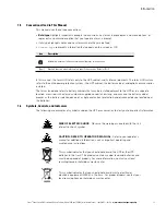
Page 11: ...se the battery cabinet breaker as the battery isolation device or a single overcurrent protection and disconnect device located near the batteries 1 6 Symbols Controls and Indicators The following are examples of symbols used on the UPS or accessories to alert you to important information Icon Description Information notes call attention to important features or instructions Keys Brackets are used...

Page 12: ...PS system l Communication capabilities of the UPS system Visit www eaton com powerquality or contact an Eaton service representative for information on how to obtain copies of these manuals 1 8 Getting Help If help is needed with any of the following l Scheduling initial startup l Regional locations and telephone numbers l A question about any of the information in this manual l A question this ma...

Page 13: ...e near water or excessive humidity 95 maximum The system is not intended for outdoor use l Ensure all power is disconnected before performing installation or service l Batteries can present a risk of electrical shock or burn from high short circuit current The following precautions should be observed 1 Remove watches rings or other metal objects 2 Use tools with insulated handles 3 Do not lay tool...

Page 14: ...ce and will reduce or void the battery warranty Refer toTerms and Conditions of Sale with Battery Replacement Coverage and the Battery Replacement Price Book for more information These documents can be found at www eaton com powerquality or contact your service representative for information on how to obtain copies l Keep surroundings uncluttered clean and free from excess moisture l Observe all D...

Page 15: ...igher than 1000m 3300 ft contact an Eaton service representative for important information about high altitude operation The operating environment must meet the weight clearance and environmental requirements specified 3 2 1 Environmental Considerations The battery system installation must meet the listed guidelines Failure to follow guidelines may void your warranty l The system must be installed...

Page 16: ...perational Temperature Range 22 28 C 72 82 F l Maximum Relative Humidity 95 non condensing Table 3 1 Maximum Battery Cabinet Weight Model Weight kg lb Shipping Installed Point Loading Power Xpert 9395 1085 or 1085HR with 40 batteries 480 Vdc 2368 5221 2327 5130 8 at 291 642 Table 3 2 UPS Cabinet Clearances From Top of Cabinet Minimum clearance over the UPS cabinet is 457 2 mm 18 minimum for ventil...

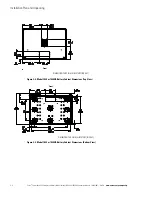
Page 17: ...nd 1085HR Installation Manual 164201687 Rev 06 www eaton com powerquality 3 3 Figure 3 1 Model 1085 or 1085HR Battery Cabinet Dimensions Front View Figure 3 2 Model 1085 or 1085HR Battery Cabinet Dimensions Right Side View DIMENSIONS ARE IN MILLIMETERS INCHES DIMENSIONS ARE IN MILLIMETERS INCHES ...

Page 18: ...and 1085HR Installation Manual 164201687 Rev 06 www eaton com powerquality Figure 3 3 Model 1085 or 1085HR Battery Cabinet Dimensions Top View Figure 3 4 Model 1085 or 1085HR Battery Cabinet Dimensions Bottom View DIMENSIONS ARE IN MILLIMETERS INCHES Front DIMENSIONS ARE IN MILLIMETERS INCHES Front ...

Page 19: ... the battery isolation device or a single overcurrent protection and disconnect device located near the batteries l Each battery cabinet has its own overcurrent protection device with a built in shunt trip or UVR for 9395C feature that must be used in all configurations l Refer to the appropriate Power Xpert 9395 UPS Installation and Operation manual listed in paragraph 1 7 for UPS cabinet conduit...

Page 20: ...275 2 500 1 2 GND 2 5 300 300 3 500 1 2 GND 2 5 550 400 3 500 1 2 GND 2 5 550 450 3 500 1 2 GND 2 5 550 500 4 500 1 2 GND 2 5 550 550 4 500 1 2 GND 2 5 825 600 5 500 1 2 GND 2 5 825 650 5 500 1 2 GND 2 5 825 750 6 500 1 2 GND 2 5 825 825 6 500 1 2 GND 2 5 1100 900 7 500 1 2 GND 2 5 1100 1000 7 500 1 2 GND 2 5 1100 1100 7 500 1 2 GND 2 5 All All Ground 3 1 2 GND 2 5 NOTE This table is not to be use...

Page 21: ...he UPS manual Table 3 5 External Power Wiring Requirements for Power Xpert 9395C Model 1085 1085HR Battery Cabinet to UPS or to Common Disconnect UPS Model Power Xpert 9395C kVA kW Minimum Number of Cabinets per UPS Battery Terminal Minimum Conductor Size AWG 90 C Copper Number per Pole Wires Conduit Conduit EMT Trade Size 1100 1000 8 500 1 2 GND 2 5 1100 1100 8 500 1 2 GND 2 5 NOTE This table is ...

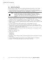
Page 22: ...interface wiring between the UPS and battery cabinet is to be provided by the customer l When installing external interface wiring for example battery breaker shunt trip to the battery cabinet interface terminals conduit must be installed between the battery cabinets and the UPS cabinet Install the interface wiring in separate conduit from the power wiring l The Battery Aux and 48 Vdc Shunt Trip o...

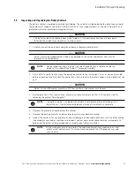
Page 23: ...let jack s forks between the pallet supports on the bottom of the unit CAUTION Do not tilt the UPS cabinet more than 10 from vertical or the cabinet may tip over 3 Set the pallet on a firm level surface allowing a minimum clearance of 3m 10 ft on each side for removing the cabinet from the pallet 4 Remove the protective covering from the cabinet 5 Remove the packing material and discard or recycle...

Page 24: ...ing 3 10 Eaton Power Xpert 9395 Integrated Battery Cabinet Model 1085 and 1085HR Installation Manual 164201687 Rev 06 www eaton com powerquality Figure 3 5 Power Xpert 9395 Model 1085 or 1085HR Battery Cabinet as Shipped on Pallet ...

Page 25: ...r to the applicable Power Xpert 9395 UPS Installation and Operation Manual listed in paragraph 1 7 for UPS cabinet conduit and terminal specifications and locations l The conduit landing plates are to be removed to add conduit landing holes as required Plate material is 16 gauge steel 1 5 mm 0 06 thick l The recommended installation location for battery cabinets located adjacent to the UPS is on t...

Page 26: ... the cabinet Locate the four 1 2 jacking bolts and install them in the threaded holes in the front and rear supports Place a floor protector underneath each jacking bolt and screw the bolts down against them The floor protectors protect the floor from being marred by the jacking bolts Retain the remaining parts of the field kit for later use Figure 4 1 Removing Shipping Supports 5 Loosen but do no...

Page 27: ...pported by the jacking bolts 9 Remove the jacking bolts and discard or recycle them in a responsible manner 10 Remove the hardware holding the front rear and side supports to the cabinet base Discard or recycle the hardware and support brackets in a responsible manner 11 Roll the battery cabinet to its final location 12 Repeat Steps 3 through 11 for each cabinet you are preparing to install 4 3 Mo...

Page 28: ...ling feet until the cabinet is not resting on the casters and the cabinet is level 4 Remove the cosmetic cover and hanger brackets from the appropriate side or sides of the battery cabinets depending on the position of the cabinets Save covers screws and brackets for later use 5 Roll the next battery cabinet to be joined to an area near the appropriate side of the first battery cabinet 6 Push the ...

Page 29: ...lat bracket over the hinge screw holes Replace the screws in the hinges securing the bracket to the cabinets see Figure 4 5 10 Locate the large flat bracket from the field kit Place the bracket over the bolts on the bottom side of the adjacent lower hinges on the battery cabinets see Figure 4 6 Figure 4 3 Battery Cabinet to Battery Cabinet Joining Brackets NOTE Two cabinet joining brackets are pro...

Page 30: ...e 4 4 Hardware is provided on each ground stud 13 If installing additional battery cabinets repeat Steps 4 through 12 to join each additional battery cabinet otherwise proceed to Step 14 14 If not already installed mount the hanger brackets to the top appropriate side of the last battery cabinet using M4 screws see Figure 4 5 15 If not already installed hang the side panel on the hanger brackets a...

Page 31: ...ilation grill on top of the unit Do not remove the debris shield until installation is complete However remove the shield before using the battery cabinet Once the debris shield is removed do not place objects on the ventilation grill NOTE Remove the battery cabinet top or bottom conduit landing plate to drill or punch conduit holes see Figure 4 6 NOTE Wiring is installed externally between each b...

Page 32: ...tions as necessary Figure 4 6 Battery Cabinet Conduit and Wire Entry Locations 3 If wiring to a battery disconnect proceed to Step 6 otherwise proceed to Step 4 4 Follow the required battery cable routing instructions specified in Section 3 2 2 above Route and connect the other end of the battery cables to the UPS cabinet battery input terminals E4 and E5 and ground terminals Refer to the applicab...

Page 33: ...efer to the applicable Power Xpert 9395 Installation and Operation manual listed in paragraph 1 7 for UPS cabinet terminal locations and termination requirements 8 Repeat Steps 1 through 7 for each battery cabinet and then proceed to paragraph 4 3 3 Figure 4 7 1085 Battery Power and Interface Terminal Locations Cabinet to UPS Negative Terminals Cabinet to UPS Positive Terminals Interface Terminal ...

Page 34: ...erface Terminal Block TB1 and Connectors J3 And P3 see Figure 4 11 For details Battery Breaker Ground Terminal Inter Cabinet Wiring Access to Route Interface Wires Between Cabinets Inter Cabinet Wiring Access to Route Interface Wires Between Cabinets EMP Mounting Location if installed Ground Stud Ground Stud NOTE Use pressure and bus bar terminations as necessary for connecting cables between the ...

Page 35: ...See Figure 4 11 through Figure 4 13 and Figure 5 6 through Figure 5 8 5 If wiring a battery disconnect proceed to Step 9 otherwise proceed to Step 6 6 Route the Shunt Trip or UVR and Aux battery wiring from the first battery cabinet TB1 terminals see Figure 4 9 to Figure 4 11 and Figure 5 6 to the UPS interface terminals through conduit Use top or bottom entry 7 Connect the wiring to terminal stri...

Page 36: ...pert 9395 Installation and Operation manual listed in paragraph 1 7 for UPS cabinet terminal locations and assignments and termination requirements 13 Proceed to paragraph 4 3 4 Figure 4 9 Battery Breaker Interface Wiring Table 4 1 TB1 Interface Connections Terminal TB1 Name Description 1 CB1 Aux 1 Switch NC Auxiliary battery breaker dry contacts Not used 2 CB1 Aux 1 Switch Com 3 CB1 Aux 1 Switch ...

Page 37: ...y Undervoltage Trip 8 CB1 Aux 2 Switch NC Auxiliary battery breaker dry contact Not used 9 CB1 Aux 2 Switch Com Battery Aux Return Contacts used to indicate whether UPS battery breaker or disconnect is open or closed 10 CB1 Aux 2 Switch NO Battery Aux 11 48 Vdc Battery Undervoltage Trip Contacts used to open battery breaker or disconnect 12 48 Vdc Battery Undervoltage Trip Battery Cabinet 1 First ...

Page 38: ...com powerquality Figure 4 11 Terminal Block TB1 Connector Assignments First Cabinet 1 2 3 4 5 6 7 8 9 11 10 12 P3 From UPS contractor supplied wiring To Next Battery Cabinet TB1 Jumper Position for First Cabinet in Multi Cabinet Installations Battery Aux Battery Aux Return 48 Vdc Battery Shunt Trip or UVR 48 Vdc Battery Shunt Trip or UVR ...

Page 39: ...or Assignments Middle Cabinets Figure 4 13 Terminal Block TB1 Connector Assignments Last Cabinet 1 2 3 4 5 6 7 8 9 11 10 12 J3 P3 From Previous Battery Cabinet To Next Battery Cabinet TB1 Jumper Position for Middle Cabinets in Multi Cabinet Installations 1 2 3 4 5 6 7 8 9 11 10 12 J3 P3 From Previous Battery Cabinet Not Used TB1 Jumper Position for Last Cabinet in Multi Cabinet Installations ...

Page 40: ...ete the battery string connections see Figure 4 14 3 FOR 1085HR ONLY Connect the string of battery trays by mating the loose black connector with the blue locking mechanism from each tray to the fixed black connector mounted on the front edge of the tray below Connect the top and bottom tray connectors to the mating cabinet connectors to complete the battery string connections see Figure 4 15 4 Re...

Page 41: ...t ensures all hardware cables and other equipment have been installed Completing all items on the checklist will ensure a smooth installation Make a copy of the Installation Checklist before filling it out and retain the original After completing your installation a service representative will be able to verify the operation of the battery cabinet and commission it to support the critical load The...

Page 42: ...tioning equipment is installed and operating correctly o The area around the installed UPS system is clean and dust free It is recommended that the UPS be installed on a level floor suitable for computer or electronic equipment o Adequate workspace exists around the UPS and other cabinets o Adequate lighting is provided around all UPS equipment o A 120 Vac service outlet is located within 7 5 mete...

Page 43: ..._______________________________________ ________________________________________________________________________ ________________________________________________________________________ ________________________________________________________________________ ________________________________________________________________________ ____________________________________________________________________...

Page 44: ...Installation Checklist 4 20 Eaton Power Xpert 9395 Integrated Battery Cabinet Model 1085 and 1085HR Installation Manual 164201687 Rev 06 www eaton com powerquality This page intentionally left blank ...

Page 45: ... 275 kVA Plus 1 UPS Figure 5 2 Battery Cabinet Oneline with Disconnect Common Battery 275 and 500 kVA RT and 275 kVA Plus 1 UPS UPS Cabinet Four Cabinets Maximum Battery Cabinet Battery Cabinet Battery Cabinet Battery Cabinet NOTE See paragraph 3 2 2 for wiring installation notes and Table 3 3 for wiring requirements E4 E5 I O UPS Cabinet Four Cabinets Maximum Battery Cabinet Battery Cabinet Batte...

Page 46: ...uality Figure 5 3 Battery Cabinet Oneline Separate Battery 275 kVA Plus 1 and 500 kVA RT UPS UPS Cabinet Three Cabinets Maximum Battery Cabinet Battery Cabinet Battery Cabinet NOTE See paragraph 3 2 2 for wiring installation notes and Table 3 3 for wiring requirements E4 E5 I O Three Cabinets Maximum Battery Cabinet Battery Cabinet Battery Cabinet E4 E5 UPM 1 UPM 2 ...

Page 47: ...with Disconnect Separate Battery 275 kVA Plus 1 and 500 kVA RT UPS UPS Cabinet Four Cabinets Maximum Battery Cabinet Battery Cabinet Battery Cabinet Battery Cabinet NOTE See paragraph 3 2 2 for wiring installation notes and Table 3 3 for wiring requirements Battery Disconnect E4 E5 I O E4 E5 UPM 1 UPM 2 Four Cabinets Maximum Battery Cabinet Battery Cabinet Battery Cabinet Battery Cabinet Battery D...

Page 48: ...allation Manual 164201687 Rev 06 www eaton com powerquality 5 2 Schematics Figure 5 5 show the battery cabinet three pole internal power wiring Figure 5 6 through Figure 5 8 show the battery cabinet breaker CB1 control wiring Figure 5 5 1085 or 1085HR Battery Cabinet with Three Pole Breaker Power Wiring Schematic ...

Page 49: ...lation Manual 164201687 Rev 06 www eaton com powerquality 5 5 Figure 5 6 Battery Cabinet Breaker CB1 Control Wiring Schematic First Cabinet Figure 5 7 Battery Cabinet Breaker CB1 Control Wiring Schematic Middle Cabinets First Cabinet in Multi Cabinet Installations Middle Cabinets in Multi Cabinet Installations ...

Page 50: ...er Xpert 9395 Integrated Battery Cabinet Model 1085 and 1085HR Installation Manual 164201687 Rev 06 www eaton com powerquality Figure 5 8 Battery Cabinet Breaker CB1 Control Wiring Schematic Last Cabinet Last Cabinet in Multi Cabinet Installations ...

Page 51: ...resentative If the string requires service refer to the battery manufacturer s operating manual for instructions on battery maintenance or contact an Eaton service representative Observe these precautions when working on or around batteries l Remove watches rings or other metal objects l Use tools with insulated handles l Wear rubber gloves and boots l Do not lay tools or metal parts on top of bat...

Page 52: ...tions 6 4 Recycling the Used Battery or UPS Contact your local recycling or hazardous waste center for information on proper disposal of the used battery or UPS WARNING l Do not dispose of the battery or batteries in a fire Batteries may explode Proper disposal of batteries is required Refer to your local codes for disposal requirements l Do not open or mutilate the battery or batteries Released e...

Page 53: ...nts communiquer avec le centre régional de récupération réutilisation ou d élimination des déchets dangereux CAUTION Do not discard waste electrical or electronic equipment WEEE in the trash For proper disposal contact your local recycling reuse or hazardous waste center ATTENTION Ne pas éliminer les déchets d équipements électriques et électroniques DEEE aux ordures Pour connaître la méthode d él...

Page 54: ...Maintenance 6 4 Eaton Power Xpert 9395 Integrated Battery Cabinet Model 1085 and 1085HR Installation Manual 164201687 Rev 06 www eaton com powerquality This page intentionally left blank ...

Page 55: ......

Page 56: ... P 164000483 1 P 164201687 6 ...

Reviews: