10
Eastwood Technical Assistance: 800.343.9353 >> [email protected]
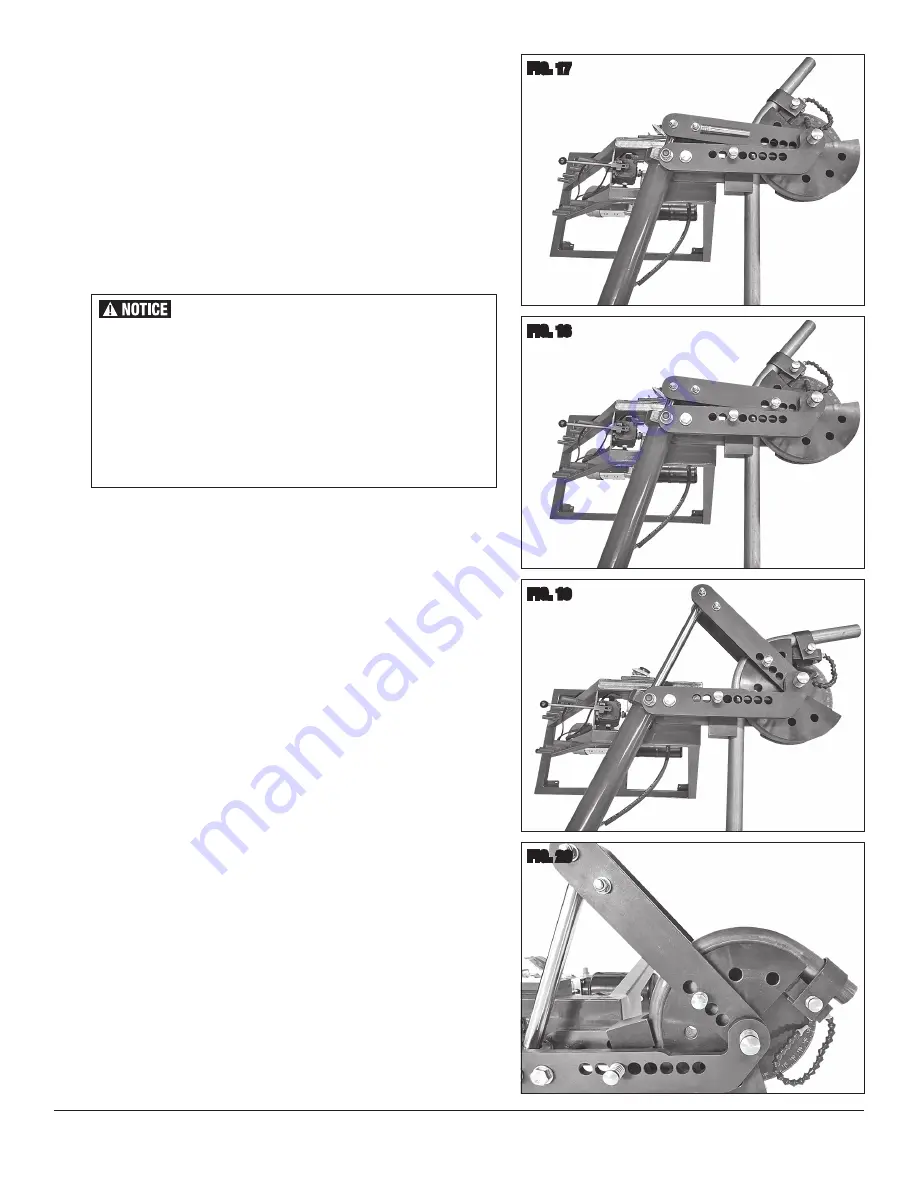
FIG. 17
At the end of the stroke, the Die Drive Pin
[K]
must be pulled out and repositioned in the
Drive Arms closer toward the center of the Die as follows:
• Very lightly, modulate the Actuating Handle upward to retract the Cylinder slightly
to relieve any tension in the workpiece and Die components.
• Pull the Die Drive Pin
[K]
from the Die and Die Drive Arms
(FIG 17)
and fully
retract the Cylinder by moving the Actuator Handle upward.
• Move the Die Drive Pin
[K]
to another hole further inward on the Die
(FIG 18)
.
NOTE:
If the pin holes in the Die Drive Arms do not align with the next available
Die hole, the Cylinder may be advanced slightly to allow Pin alignment.
• As previously, slowly and steadily push downward on the Bender Handle, continu-
ing to further bend the workpiece tubing. Watch the position of the Pointer on the
Degree Wheel carefully as the desired bend angle is approached
(FIG 19)
.
• To achieve more bending range as needed; the above steps may need to be
repeated until the desired bend angle is reached
(FIG 20)
.
There will be a certain amount of “springback” meaning that the
Pointer must be pushed several degrees past the Degree Wheel
target then allow it to “spring back” to the final degree mark.
This varies widely according to the particular material, diameter
and thickness. Chromoly and high carbon steel will generally
have more “springback” than milder steels and aluminum. This
is one reason that some “trial and error” must be performed to
explore the properties of the material before working on a final
project piece.
FIG. 18
FIG. 19
FIG. 20


