


Level Sensor 8–2
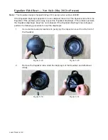
1.
The configuration above is a field or shop configuration. You can also use a
regulated air source into tube #1 for a shop configuration.
2.
Connect the three pieces of tubing to the pump or regulated air source, the
monometer and the level sensor assembly in the configuration shown above.
3.
Pressurize the level sensor assembly to 82 inches to 90 inches of water column in air
(approximately 3 psi).
4.
Close the isolation valve.
5.
After 40 seconds, record the monometer reading.
6.
After another 30 seconds, record the monometer reading again.
7.
Subtract the last reading from the first reading.
The results must be no more than 0.5 inch of loss for hardwired assemblies manufactured
before 8/25/2009 or serial number 353742 and no more than .01 inch for units manufactured
after 8/25/2009 or serial number 353742.
Level Sensor Leak Troubleshooting & Repair
If a substandard result occurs, perform the following procedure to determine where the leak is
occurring and where to repair the level sensor assembly.
1.
While the assembly is under pressure (82 inches to 90 inches of water in air), spray
soapy water or leak detector around the liquid tight cord grip, the Equalizer tube, the
barbed fitting, the joint between the two assembly halves, the cable and T portion of
the over-mold, and the test assembly.
2.
Lay the assembly on its side and spray around the column holes in the bell area.
3.
Make any necessary repairs and retest the level sensor assembly.
4.
Snip off 1/2 inch of the tubing to ensure a good seal. Reinstall the Equalizer tube
onto the barbed fitting.
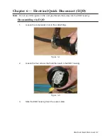
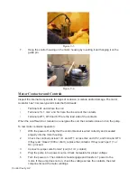
Level Sensor Disassembly
1.
Loosen the four Phillips head screws that hold the level sensor assembly together
(Fig. 8-4). Separate the two columns (Fig. 8-5).
Figure 8-4
Figure 8-5
Summary of Contents for Extreme Series
Page 1: ...Service Manual E One Extreme Grinder Pumps 240V 60 Hz Hardwired Controls...
Page 2: ......
Page 32: ...Pump End 5 8 Figure 5 9a D Series Pump Exploded View...
Page 33: ...Pump End 5 9 Figure 5 9b W Series Pump Exploded View...
Page 34: ...Pump End 5 10 Figure 5 9c Gatorgrinder GH Series Pump Exploded View...
Page 35: ...Pump End 5 11 Figure 5 9d IH091 Pump Exploded View...
Page 36: ...Pump End 5 12...
Page 58: ...Level Sensor 8 10 Figure 8 35 Level Sensor Assembly Exploded View all hardwired pumps...
Page 70: ...Mechanical Seal Assembly 11 2...
Page 75: ......


