Troubleshooting 2–9
Possible Causes
Troubleshooting Steps
Blocked discharge line,
worn stator or leak in
pump discharge assem
-
bly
Check the amperage. If the amperage is high (8 amps or higher), turn off the
pump and check the discharge line for blockage. Confirm that the pump has
not been damaged by disconnecting the discharge piping and recycling the
fluid in the tank. Turn the pump power on and check the amperage. If the am-
perage remains high, replace the pump and return the failed pump to shop for
possible repair. If amperage returns to normal, clear blockage in discharge line
and re-check amperage.
If the amperage is low (4.9 amps or less), the pump must be pulled and the
stator (and possibly the rotor) replaced, or the leaking discharge line repaired.
The cause of the stator and/or rotor failure must be determined and corrected
before reinstallation or the pump will fail prematurely again.
Chapter 5 – Pump
End
describes how to identify and correct causes of stator and rotor wear.
Alarm On — Pump Running but not Pumping
Table 2–8
Possible Causes
Troubleshooting Steps
Incorrect voltage
Check the voltage at a location nearest the pump, such as the junction box or
EQD. The correct voltage is listed on the pump nameplate.
Note:
Voltage must
be within 10 percent of nameplate voltage (240V: 216V to 264V; 120V: 108V to
132V). 208V requires a buck boost transformer.
Plugged Equalizer
Check the Equalizer tube and ensure it is not crimped or pinched.
Low fluid level
Check the tank for sufficient fluid to operate the pump. Insufficient fluid may
indicate a problem with the alarm wiring, alarm sensing line, or alarm switch.
Chapter 8 – Level Sensor
and
Chapter 9 – Control Cavity
describe the steps for
checking the alarm wiring and controls.
Wet or corroded controls Inspect the electrical controls and replace any wet or corroded controls. See
Chapter 9 – Control Cavity.
Inoperative control
Test the controls as described in
Chapter 9 – Control Cavity.
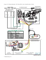
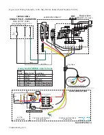
Alarm On — Pump not Operating
Table 2–9
Troubleshooting
Summary of Contents for Extreme Series
Page 1: ...Service Manual E One Extreme Grinder Pumps 240V 60 Hz Hardwired Controls...
Page 2: ......
Page 32: ...Pump End 5 8 Figure 5 9a D Series Pump Exploded View...
Page 33: ...Pump End 5 9 Figure 5 9b W Series Pump Exploded View...
Page 34: ...Pump End 5 10 Figure 5 9c Gatorgrinder GH Series Pump Exploded View...
Page 35: ...Pump End 5 11 Figure 5 9d IH091 Pump Exploded View...
Page 36: ...Pump End 5 12...
Page 58: ...Level Sensor 8 10 Figure 8 35 Level Sensor Assembly Exploded View all hardwired pumps...
Page 70: ...Mechanical Seal Assembly 11 2...
Page 75: ......


