Start-Up Procedure 4–1
Chapter 4 — Start-Up Procedure
Station Inspection
Inspect the following:
1.
Proper burial depth (1 to 4 inches below the hinged cover/transition joint).
2.
The ground must be graded to prevent water from pooling around the station.
3.
Free from damage and leaks.
4.
The Equalizer tube/power cable must be hung at the top of the station and not lay on
the pump or in wastewater.
5.
Electrical shroud must be attached.
6.
The tray cable must not be exposed outside the tank.
7.
Ensure the discharge valve in the station is open.
8.
Ensure that the supply cable connector beneath the cover shroud is tightened
securely.
Alarm Panel Inspection
Inspect the following:
1.
Proper wiring. Refer to the wiring diagram inside the panel door.
2.
Free from damage.
3.
Unshielded wires must not be exposed outside of panel.
4.
Conduits must be sealed.
5.
Test incoming line voltage. If the voltage varies more than 10 percent of the
nameplate voltage, do not continue. Rectify the voltage problem.
Voltage, Continuity and Cable Insulation Integrity Tests
Refer to
Chapter 2 – Troubleshooting
to perform these tests. Read all meter instructions for
safety information, scale setting, and proper operational procedures.
Take test points in the alarm panel. The colors listed in Tables 2-3 through 2-6 are the leads
coming from the station and connect in the panel. Using the tables, perform the checks to
ensure appropriate readings.
The values listed are average numbers. Allow the meter at least 5 seconds to obtain a correct
reading. The meter may give a false reading while bleeding off to an open circuit. This is the
impedance of the wire bleeding off and is expected.
WARNING!
Always perform continuity checks with the power off!
Use your volt meter to ensure no power is applied
to the pump circuits.
Summary of Contents for Extreme Series
Page 1: ...Service Manual E One Extreme Grinder Pumps 240V 60 Hz Hardwired Controls...
Page 2: ......
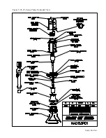
Page 32: ...Pump End 5 8 Figure 5 9a D Series Pump Exploded View...
Page 33: ...Pump End 5 9 Figure 5 9b W Series Pump Exploded View...
Page 34: ...Pump End 5 10 Figure 5 9c Gatorgrinder GH Series Pump Exploded View...
Page 35: ...Pump End 5 11 Figure 5 9d IH091 Pump Exploded View...
Page 36: ...Pump End 5 12...
Page 58: ...Level Sensor 8 10 Figure 8 35 Level Sensor Assembly Exploded View all hardwired pumps...
Page 70: ...Mechanical Seal Assembly 11 2...
Page 75: ......


