6
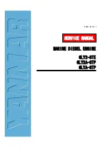
MAP hose
connection
LED
Cylinders 1 & 2
Cylinders 3 & 4
LED
Indicator
even when not firing the plugs. Use the main buss switch (or breakers if
necessary) to power down the ignitions when not in use
6.
”6” is a courtesy (optional) connection to provide a digital tack signal – two
pulses per revolution.
Note 1: Collect your tack signal from only one, not
both, ignitions. This applies to dual E-MAG ignitions as well as split
systems (E-MAG in tandem with a magneto or other EI). Note 2:
Your E-
MAG will generate a tack signal even when it is disabled at the key (or
other) p-lead ignition switch, so you won’t loose tack when you switch the
E-MAG OFF during a preflight ignition check. Note 3: E-MAG’s tack
output is a courtesy feature that is unrelated to the ignition’s primary
purpose. Due to the variety of instrument options available, our ability to
support and troubleshoot tack interface issues is limited.
MAP Sensor
Connect one end of the sensor hose
to the MAP nipple on the back of the
ignition case next to the coil base, and
secure with nylon clamp. Route the
line to a convenient connection point
(connecting hardware not included)
where you can tee into the line going
to your manifold pressure gauge.
Note 1:
The MAP sensor is a fail-safe
input; i.e. if the tube comes loose or
fails in-flight, timing will retard to an
operable, but much less efficient
range.
Spark Plugs & Harness
Post Assignments
– The plug wire
assignments are as follows:
1.
Cylinders 1 and 2 connect to the
coil pair nearest the LED indicator
2.
Cylinders 3 and 4 connect to the
coil pair furthest from the LED
indicator.
Note: It does not matter which cylinder is
connected to which post within a given