15
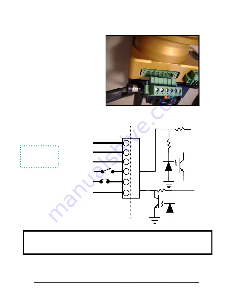
Wiring Diagram
*Series 113 ignitions provide a 12-volt tack signal with two pulses per revolution. Note: Tack signal
is NOT a primary ignition function. It is a courtesy signal we are happy to provide. Due to the
variety of instruments available, we can provide only limited tack signal trouble shooting and/or
customer support.
Connector Plug
(viewed from cage
screw side)
Opto Isolator
Opto Isolator
Inside
Case
Outside
Case
(Power and ground wiring should be
18 gauge. Other wires can be 20
gauge.)
+5 Volts
1.
To ground on engine case
1
4
. P-Lead (ignition switch to ground
stops ignition firing)
4
5.
Aircraft Power (+13.8vdc) through
3(P-MAG) or 5(E-MAG) amp breaker
5
6.
Optional Tack Output* - 12-volt
pulse 20 millisecond long - 2 ppr
6
2
Control Alternate
3
Control Alternate
Jumpers
2 & 3
for low advance
– see Variable
Timing Limit
+12 Volts


