5
Anchor Screws
Controls
Control Wiring
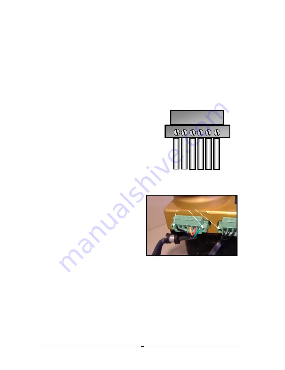
– Control leads are connected to the ignition via a Control Plug that
captures each lead with a screw cage mechanism. The plug is then attached to the
ignition and secured with anchor screws on either side. A wiring diagram is included
at the end of this manual. The numbering system for the plug terminals is 1 thru 6 as
viewed looking at the cage screw heads with wires oriented below (see fig). The
wire/plug assignments are as follows
:
Use the cushioned anchor strap to provide a
mechanical strain relief for the wires.
1.
“1” connects directly to a nearby
engine case ground using 18 gauge
wire.
Note 1: You cannot rely on the
ignition’s mechanical attachment to the
engine to provide ground. Aluminum
anodizing acts as an electrical
insulator, so the clamp connection to
the anodized flange will not serve as a
reliable ground.
2.
“2” Control Alternate (future use)
3.
“3” Control Alternate (future use)
4.
“4” connects to your ignition
ON/OFF (ground) p-lead switch
using 20 gauge wire or larger.
Note 1: If you are replacing a
magneto, your old P-Lead can
serve this purpose, and may
already be wired to a suitable
switch. Note 2: Non-starting
magnetos require a mechanism to
prevent them from firing during
start-up. Keyed ignition switches
have a jumper on the back that serves this purpose. When installing an E-
MAG in place of a non-starting magneto that was controlled by such a
switch, make sure you remove this jumper. You do NOT want a start-up
block on any circuit controlling your E-MAG(s).
5.
“5” connects to your main 12 volt aircraft buss through a dedicated circuit
breaker (not provided) using 18 gauge wire. E-MAGs should use a 5-amp
breaker, and P-MAGs should use a 3-amp switchable breaker. The
switch is needed to test the P-MAG internal alternator during ground run
up – see Operating Notes.
Note 1: Whenever the aircraft buss is
powered up, the ignition is “awake”. It draws a small amount of current
Tack
1
Control Plug
4
5 6
3
A
L
T
2
A
L
T


