


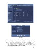
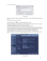

184
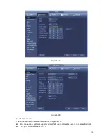
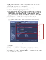
Figure 4-98
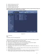
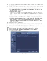
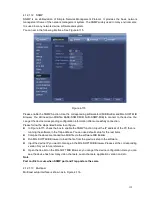
4.12 Network
4.12.1.1 TCP/IP
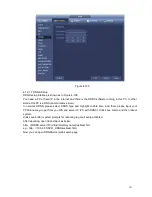
The single network adapter interface is shown as in Figure 4-99 and the dual network adapters interface
is shown as in Figure 4-100.
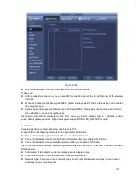
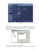
Network Mode : Includes multiple access, fault tolerance, and load balancing
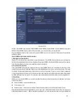
Multiple-address mode: eth0 and eth1 operate separately. You can use the services such as
HTTP, RTP service via etho0 or the eth1. Usually you need to set one default card (default setup
is etho) to request the auto network service form the device-end such as DHCP, email, FTP and
etc. In multiple-address mode, system network status is shown as offline once one card is
offline.
Network fault-tolerance: In this mode, device uses bond0 to communicate with the external
devices. You can focus on one host IP address. At the same time, you need to set one master
card. Usually there is only one running card (master card).System can enable alternate card
when the master card is malfunction. The system is shown as offline once these two cards are
both offline. Please note these two cards shall be in the same LAN.
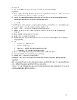
Load balance: In this mode, device uses bond0 to communicate with the external device. The
eth0 and eth1 are both working now and bearing the network load. Their network load are
general the same. The system is shown as offline once these two cards are both offline. Please
note these two cards shall be in the same LAN.
Default Network Card: Please select eth0/eth1/bond0(optional) after enable multiple -access
function
Main Network Card: Please select eth0/eth1 (optional).after enable multiple access function.
Note: The dual-Ethernet port series support the above three configurations and supports
functions as multiple-access, fault-tolerance and load balancing.
Summary of Contents for ELI-SIP2-NVR8
Page 84: ...172 Figure 4 81 Figure 4 82 ...
Page 85: ...173 Figure 4 83 Figure 4 84 ...
Page 91: ...179 Figure 4 89 Figure 4 90 ...
Page 92: ...180 Figure 4 91 Figure 4 92 ...
Page 93: ...181 Figure 4 93 Figure 4 94 ...
Page 95: ...183 Figure 4 96 Figure 4 97 ...
Page 182: ...270 The motion detect interface is shown as in Figure 5 54 Figure 5 54 Figure 5 55 ...
Page 183: ...271 Figure 5 56 Figure 5 57 Figure 5 58 ...
Page 187: ...275 Figure 5 62 Figure 5 63 ...


