
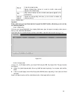
274
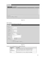
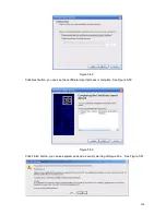
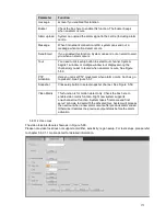
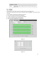
Figure 5-60
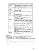
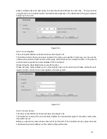
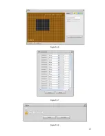
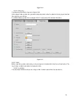
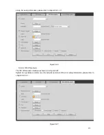
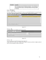
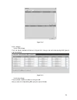
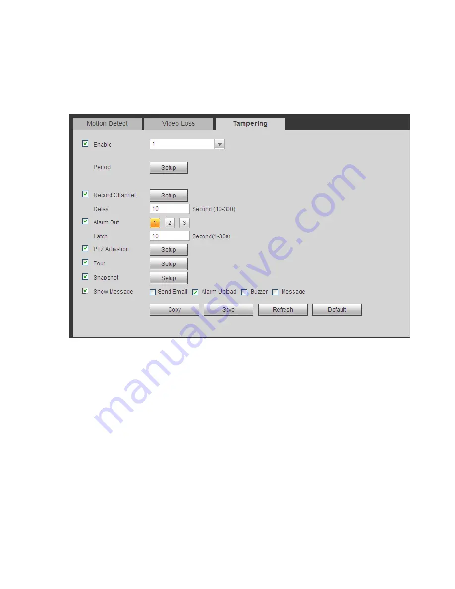
5.8.3.1.3 Tampering
The tampering interface is shown as in Figure 5-61.
After analysis video, system can generate a tampering alarm when the detected moving signal reached
the sensitivity you set here.
For detailed setups, please refer to chapter 5.8.3.1.1 motion detect for detailed information.
Figure 5-61
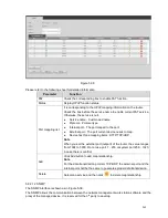
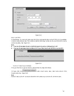
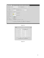
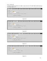
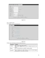
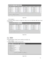
5.8.3.2 Alarm
Before operation, please make sure you have properly connected alarm devices such as buzzer. The
input mode includes local alarm and network alarm.
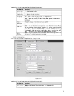
5.8.3.2.1 Local Alarm
The local alarm interface is shown as in Figure 5-62. It refers to alarm from the local device.
Summary of Contents for ELI-SIP2-NVR8
Page 84: ...172 Figure 4 81 Figure 4 82 ...
Page 85: ...173 Figure 4 83 Figure 4 84 ...
Page 91: ...179 Figure 4 89 Figure 4 90 ...
Page 92: ...180 Figure 4 91 Figure 4 92 ...
Page 93: ...181 Figure 4 93 Figure 4 94 ...
Page 95: ...183 Figure 4 96 Figure 4 97 ...
Page 182: ...270 The motion detect interface is shown as in Figure 5 54 Figure 5 54 Figure 5 55 ...
Page 183: ...271 Figure 5 56 Figure 5 57 Figure 5 58 ...
Page 187: ...275 Figure 5 62 Figure 5 63 ...


