background image

47

48

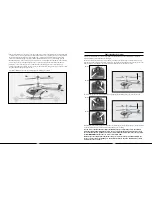
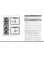
Exploded View 

Reference 

Number

Exploded View 

Reference 

Number

Description (Quantity 

Required)

Description (Quantity 

Required)

Included In Item 

Number

Included In Item 

Number

001  Stabilizer Flybar Rubber Tip (2) 

EFLH1219

002  Stabilizer Flybar Weight (2) 

EFLH1219

003  Stabilizer Flybar (1)  

EFLH1219

004  Screw (2) M2x3mm  

EFLH1242

005  Stabilizer Flybar Link (1)  

EFLH1219

006  Stabilizer Flybar Linkage Rod (1)  

EFLH1219

007  Stabilizer Flybar Link (1)  

EFLH1219

008  1 .2 x 6mm Screw (4)  

EFLH2007

009  Upper Main Blade (2)  

EFLH1221

010  M2 x 2 .5mm Screw (5)  

EFLH2007

011  Lower Main Blade (2)  

EFLH1220

012  Upper Rotor Head Cap (1)  

EFLH1242

013  Upper Rotor Head (1)   

EFLH1242

014  Upper Rotor Head Set Screw (1)  

EFLH1242

015   Inner Shaft for Aluminum Head/Hub 

EFLH1241

016   . Bearing 2mm x 6mm x 3mm (2) 

EFLH1121

017   Bearing Holder (1)  

EFLH1217

018  Lower Rotor Head (1)  

EFLH1217

019  Upper Swashplate (1)  

EFLH1216

020  Lower Rotor Head/Swash Linkage (2) 

EFLH1217

021  Servo Pushrod Control Link (2) 

EFLH1218

022  Servo Pushrod Control Pushrod (2) 

EFLH1218

023  Bearing 7mm x 13mm x 4mm (1) 

EFLH1216

024  Lower Swashplate (1)  

EFLH1216

025  Outer Shaft Retaining Collar (1)  

EFLH1214

026  Outer Shaft (1)  

EFLH1213

027  Main Motor Left (1)  

EFLH1210


Main Motor Right (1)  

EFLH1211

028  Pinion Gear Left (1)  

EFLH1210


Pinion Gear Right (1)  

EFLH1211

029  Main Frame (1)  

EFLH1254

030  AR6100e Receiver (1 

SPMAR6100E

031  3in1CtrlUntMixer/ESC/Heading Lock Gyro  EFLH2001
032  Bearing 4mm x 8mm x 3mm (2 

EFLH1215

033  1 .7 x 4mm Screw (8)  

EFLH2007

034  Silicon Tube Section   

EFLH1158

035  Body Mount Rod 2x38mm (1)  

EFLH2005

036  Servo Mount (1)  

EFLH1254

037  Super Sub-Micro Servo (2)  

EFLRS60

038  1 .7 x 4mm Screw (8)  

EFLH2007

039  Horizontal Fin Antenna (2)  

EFLH2006

040  Vertical Fin (1)  

EFLH2006

041  Horizontal Fin Screw (2)  

EFLH2007

042  Horizontal Fin (1)  

EFLH2006

043  Step Washer (1)  

EFLH2007

044  Outer Shaft Main Gear (1)  

EFLH1213

045  Inner Shaft Main Gear (1)  

EFLH1212

046  Inner Shaft Retaining Collar (1) 

EFLH1214

047  M2 x 4mm Screw (6)  

EFLH2007

048  MD520N Battery Support Rear (1) 

EFLH2004

049  MD520N Battery Support Front (1) 

EFLH2004

050  Battery Pack (1)  

EFLB0990

051  MD520N Replacement Body 

EFLH2002

052  MD520N Landing Gear Screws 

EFLH2007

053  MD520N Front Landing Gear (1)   

EFLH2003

054  MD520N Right Landing Skid (1) 

EFLH2003

055  MD520N Tail Cone (1) 

EFLH2002

056  MD520N Rear Landing Skid (1) 

EFLH2003

057  MD520N Exhaust Outlet/Nozzle  

EFLH2002

058  MD520N Rear Landing Gear (1) 

EFLH2003

059  Optional MD520N Navigation Light Set 

EFLH2009

060  MD520N Left Landing Skid (1) 

EFLH2003

061  MD520N Landing Skid Screw (4) 

EFLH2007

Exploded View Parts Listing

Exploded View

Summary of Contents for Blade CX3 MD 520N RTF

Page 1: ...eutschland GmbH Hamburger Strasse 10 25335 Elmshorn Germany Patents pending DSM and DSM2 are trademarks or registered trademarks of Horizon Hobby Inc The Spektrum trademark is used with permission of Bachmann Industries Inc Spektrum radios and accessories are exclusively available from Horizon Hobby Inc MD 520N is a registered trademark or trademark of MD Helicopters Inc and is used under license ...

Page 2: ... With the included 5 channel transmitter 2 cell 800mAh Li Po battery pack DC charger and AC adapter you ll have precise control for hovering forward flight and more with flight times of up to 10 15 minutes per charge While the Blade CX3 MD 520N is ready to fly right from the box please take the time to read through this manual completely for tips on battery safety and charging control checks flyin...

Page 3: ...4GHz EFLB0990 7 4V 800mAh 2 Cell Li Po JST Balance EFLC3110 2 3 Cell Li Po Balancing Charger 0 65A EFLC4000 AC to 12VDC 1 5 Amp Power Supply EFLH1209 Mounting Accessories Screwdriver EFLH1022 Bind Plug FUG4 Optional 4 AA batteries EFLH2009 Optional MD520N LED Navigation Light Upgrade Set Additional Required Equipment No additional equipment is required to complete your Blade CX3 MD 520N Preparing ...

Page 4: ...inuing to charge or discharge a battery that has begun to balloon or swell can result in a fire A battery that has ballooned or swollen even a small amount must be removed from service completely In the event of a crash you must quickly and safely disconnect and remove the battery from the model then place it in a safe open area away from flammable materials to observe it for at least 15 minutes S...

Page 5: ...uded with your Blade CX3 MD 520N will arrive partially charged For this reason the initial charge may only take approximately 30 50 minutes The charger requires up to 1 5 amps of 11 5 to 15 volt DC input power that can be supplied by the included AC to 12V DC 1 5 Amp Power Supply EFLC4000 for convenient charging anywhere an AC outlet is available NEVER attempt to power the charger from an AC outle...

Page 6: ... the power source Also be sure that the power source is providing the proper amount of voltage and current required to the charger After confirming the connections and that the power source is delivering the necessary voltage and current re start the charge process by connecting the battery pack Continue to monitor the charge process to ensure that no further charge errors occur Simultaneous flash...

Page 7: ...d the back until the loop material on the battery securely fastens to the hook material on the battery frame stop Center of Gravity Once the battery has been properly installed and secured you will need to check the helicopter s center of gravity If the helicopter is not properly balanced it can be difficult to control and constantly try to move forward or backward in hover To check the center of ...

Page 8: ...good idea to test the controls prior to the first flight to ensure none of the servos linkages or other parts were damaged during shipping and handling Before proceeding ensure your throttle stick and trim are at the lowest possible position Turn the transmitter on first then plug the battery into the battery lead of the 3 in 1 unit Throttle Trim Aileron Trim Elevator Trim Rudder Trim Rudder Trim ...

Page 9: ...te downward Mode 2 Mode 1 Position the helicopter to view it from the FRONT Move the elevator control stick on the transmitter forward and back to check elevator pitch control When the stick is pushed forward the servo on the right side should push the swashplate upward Mode 2 Mode 1 ...

Page 10: ...t and right to check aileron roll control When the stick is pushed to the left the servo on the left side should push the swashplate upward When the stick is pushed to the right the servo on the left should pull the swashplate downward Mode 2 Mode 1 Mode 2 Mode 1 ...

Page 11: ...connection locations are correct all controls should be functioning properly If you do encounter any problems with your Blade CX3 MD 520N responding properly to the transmitter do not fly Contact the Horizon Support Team at 877 504 0233 3 in 1 Control Unit Description Arming and Motor Control Test The unique 3 in 1 Control Unit installed on your Blade CX3 MD 520N is a lightweight combination of a ...

Page 12: ... trim may not be in their lowest possible positions Check to be sure that both the throttle stick and throttle trim are in their lowest possible position and the status LED should blink green then become solid green indicating the unit is armed and ready for flight Proceed to the next step of the checklist once the unit is armed If after blinking red the status LED turns off you do not have a posi...

Page 13: ...d forward to the front of the helicopter Next carefully snap the remaining two attachments onto the landing skids behind the landing skid struts The side of the attachment with the large hole should face outward away from the helicopter and backward to the rear of the helicopter Once you have installed all four attachments install the four screws making sure that they thread properly into the back...

Page 14: ... yourself with them before attempting your first flight The throttle stick on the transmitter controls climb descend When the throttle stick and throttle trim lever are in their lowest positions the main rotor blades will not spin Advancing the stick upward will increase the speed of the main rotor blades Increasing the speed of the main rotor blades will cause the model to climb Decreasing the sp...

Page 15: ...add left rudder trim until the nose stays as close to straight as possible Also note that further adjustments to the rudder trim can be made using the Main Motor Proportional Mix Trimmer Pot as outlined on page 34 35 Mode 2 Mode 2 Mode 1 Mode 1 Nose Yaw Left Nose Yaw Right The elevator stick controls both elevator fore and aft pitch Pushing the stick forward will pitch the nose of the helicopter d...

Page 16: ...ustments to maintain its altitude in hover Remember to keep these throttle adjustments as minimal as possible as large adjustments could result in a loss of control and or a possible crash While attempting to establish a low level hover you can also check to see if any trim adjustments are required to help keep the Blade CX3 from constantly drifting in various directions If you find the helicopter...

Page 17: ...own IMMEDIATELY to prevent over discharge of the Li Po battery pack If you continue to run the motors after noticing a loss in power it is possible to discharge the Li Po battery pack too far causing permanent damage to the pack Over discharge of the Li Po battery pack can result in shortened flight times loss of power output or failure of the pack entirely Once you have gained experience and conf...

Page 18: ...pter straight These small adjustments can be made using the rudder trim lever or rudder control stick and do not require additional adjustments of the proportional trimmer pot Gyro Gain Trimmer Pot Description and Adjustment The gain trimmer pot adjusts the gain setting value of the piezo gyro used to aid in keeping the tail of the helicopter straight on heading during flight The gain value is set...

Page 19: ...ll turn at a time Power the helicopter up again and re check the blade tracking If the tracking has improved continue to turn the ends of the linkage in one half to one full turn at a time until the tips are tracking in the same plane If the tracking has become worse after first turning the ends of the adjustable linkage in turn the ends of the linkage back out one half to one full turn at a time ...

Page 20: ...nd the new transmitter AR6100e receiver to your existing transmitter or receiver for proper operation During the binding process the smart fail safe SmartSafe positions of your system are also set With SmartSafe in case of loss of signal the throttle will go to the preset position that was stored during the binding process and all other channels will hold their last position And if the receiver AR...

Page 21: ...he motors to cool to near ambient temperature between flights battery pack changes to prevent accelerated motor wear due to excess motor heat You will find the performance and life of the 180 main motors to be very good however installation of the optional Main Motor Heat Sink EFLH1208 can help to further improve motor cooling during flight resulting in improved motor performance and longer motor ...

Page 22: ...nd the line is prohibited 5 I will operate my model aircraft using only radio control frequencies currently allowed by the Federal Communications Commission FCC Only individuals properly licensed by the FCC are authorized to operate equipment on Amateur Band frequencies 6 I will not knowingly operate my model aircraft within three 3 miles of any preexisting flying site without a frequency manageme...

Page 23: ...ody Set Black BCX 2 EFLH1271 SH 60 SEAHAWK Body Set Gray BCX 2 EFLM1913 Heat Sink Compound 5g EFLH1241 Inner Shaft for Aluminum Head Hub BCX2 3 EFLH1244 Aluminum Bearing Holder w Bearing BCX2 3 EFLH1245 Aluminum Lower Rotor Head Set BCX2 3 EFLH1246 Aluminum Swashplate Set BCX2 3 EFLH2009 LED Navigation Light Upgrade Set BCX3 Please see your favorite retailer or visit our web site www E fliteRC com...

Page 24: ... 1 EFLH1210 Main Motor Right 1 EFLH1211 028 Pinion Gear Left 1 EFLH1210 Pinion Gear Right 1 EFLH1211 029 Main Frame 1 EFLH1254 030 AR6100e Receiver 1 SPMAR6100E 031 3in1CtrlUntMixer ESC Heading Lock Gyro EFLH2001 032 Bearing 4mm x 8mm x 3mm 2 EFLH1215 033 1 7 x 4mm Screw 8 EFLH2007 034 Silicon Tube Section EFLH1158 035 Body Mount Rod 2x38mm 1 EFLH2005 036 Servo Mount 1 EFLH1254 037 Super Sub Micro...

Page 25: ...ct is not intended for use by children without direct adult supervision The Product manual contains instructions for safety operation and maintenance It is essential to read and follow all the instructions and warnings in the manual prior to assembly setup or use in order to operate correctly and avoid damage or injury Questions Assistance and Repairs Your local hobby store and or place of purchas...

Page 26: ...warranty Germany Electronics and engines requiring inspection or repair should be shipped to the following address Horizon Technischer Service Hamburger Strasse 10 25335 Elmshorn Germany Please call 49 4121 46199 66 or email us at service horizonhobby de with any questions or concerns regarding this product or warranty Declaration of Conformity in accordance with ISO IEC 17050 1 No HH20081014 Prod...

Reviews: