23
24
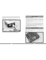
The following checklist contains the steps you must follow to ensure proper arming and operation of the 3-in-1 unit
as well as proper motor control response:
q
Each time before you fly you must ALWAYS turn on the transmitter power first before connecting
the flight battery to the 3-in-1 unit. Never connect the flight battery to the 3-in-1 unit before first
powering on the transmitter.
Also, never turn off the transmitter before disconnecting the flight battery from the 3-in-1 unit first.
q
Both the throttle stick and throttle trim MUST be in their lowest possible position in order for the
3-in-1 unit to arm the electronic speed controls for the main motors.
If this is the first test flight, or a test flight following repairs, you will also want to center the rudder, aileron and
elevator trims (see photo found on page 15 for reference) .
q
After confirming that the transmitter has been turned on and has an adequate level of battery power as displayed
by the LCD screen at the top of the transmitter, it is now safe to connect the flight battery to the 3-in-1 unit .
Note: Each time you power the transmitter on, it will enter “Bind Mode” (See pages 40-41 for
more information regarding “Bind Mode”) for a few seconds, as indicated by the red blinking LED
located under the door on the left bottom front of the transmitter. Once this LED becomes solid, the
transmitter is no longer in bind mode. We recommend waiting to connect the flight battery to the
3-in-1 unit after the transmitter has exited bind mode, otherwise the 3-in-1 may not arm properly or
as quickly.
•
With battery power applied, the 3-in-1 unit status LED will blink red, and then blink green. It is
extremely important that you do not move or sway the helicopter once the status LED begins to blink
green confirming that the initialization process and calibration of the gyro has begun.
It is OK to move
the model when the status LED is blinking red (as in the time it takes to connect the flight battery to the 3-in-1
unit and place the model at rest), as long as the model remains motionless when the status LED begins to blink
green .
•
When the status LED becomes solid green, the unit is armed and ready for flight.
Use caution as both
main motors will now run with throttle stick or throttle trim input . Do not advance the throttle stick or trim until
you are clear of the rotor blades and ready to fly .
Note: If the status LED does not become solid green, please review the following:
• If after blinking red the status LED becomes solid red, you have a positive Radio Frequency (RF) link between
the transmitter and receiver of the 3-in-1 unit, but the throttle stick and throttle trim may not be in their lowest
possible positions . Check to be sure that both the throttle stick and throttle trim are in their lowest possible
position and the status LED should blink green then become solid green indicating the unit is armed and ready for
flight . Proceed to the next step of the checklist once the unit is armed .
• If after blinking red the status LED turns off, you do not have a positive RF link between the transmitter and
receiver of the 3-in-1 unit . First, check to be sure that the transmitter has been powered on and has an adequate
level of battery power . If the transmitter was indeed powered on, power both the transmitter and 3-in-1 unit down,
then follow the steps to bind the 3-in-1 unit’s receiver to the transmitter (see pages 40–41 for more information) .
Once you have confirmed that the transmitter and receiver are properly bound, the 3-in-1 unit should now arm
normally .
If your 3-in-1 unit will not arm after following the guidelines as listed above, contact the Horizon Support Team at
877-504-0233 .
q
Once you have placed the helicopter in a safe area to test motor control, free from obstructions, and
are clear of the rotor blades, you can safely begin to power up the model.
q
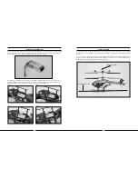
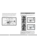
Advance the throttle stick slowly, just until the main rotor blades begin to spin . Be sure not to advance the
throttle stick too far to keep the helicopter from lifting off the ground . Note the direction that each of the main
rotor blades spins . When viewed from the top, the lower main rotor blade should spin clockwise and the upper
main rotor blade should spin counterclockwise . If either rotor blade is operating in the wrong direction, unplug the
battery, then simply reverse its motor plug polarity on the 3-in-1 unit . Note that the proper polarity is marked on
the label of the 3-in-1 unit .
q
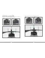
After confirming that the direction of rotation for both rotor blades is correct, it is best to confirm that both rotor
blades respond properly to rudder control inputs . With both main rotor blades spinning at a low level of power,
move the rudder stick all the way to the right . This should cause the speed of the upper main rotor blade to
increase, and the speed of the lower main rotor blade to decrease . Next, move the rudder stick all the way to the
left . This should cause the speed of the lower main rotor blade to increase and the speed of the upper main rotor
blade to decrease . If both rotor blades are not responding properly to rudder input, simply reverse the locations
of their motor plugs on the 3-in-1 unit . Note that the proper motor plug locations are marked on the label of the
3-in-1 unit .
q
After confirming both main rotor blades respond properly to rudder inputs, your Blade CX3 MD 520N is now
ready for flight . However, please be sure to review the following sections of the manual before proceeding with
the first flight .


