41
42
• In order to bind the AR6100e receiver to the transmitter, you must first insert the Bind Plug (included with your
Blade CX3 MD 520N) into the “BAT” opening on the receiver . Then you will need to power on the receiver by
connecting the flight battery into the 3-in-1 control unit BEFORE powering the transmitter on .
• When you connect the flight battery to the 3-in-1 unit with the bind plug inserted into the “BAT” opening on the
receiver, you will see an orange LED blink rapidly on the receiver itself .
• Once the orange LED on the receiver begins to blink, turn on the transmitter. The transmitter will immediately
enter bind mode . Then, once the orange LED on the receiver and the red LED on the transmitter turn solid,
the receiver is bound to the transmitter . Now you will need to power down the 3-in-1 control unit, receiver and
transmitter, and remove the bind plug from the receiver .
Note:
It is extremely important that you remove the bind plug from the receiver once it has been bound to the
transmitter . If you do not remove the bind plug the receiver will enter bind mode every time the 3-in-1 unit is
powered on .
Main Motor Care and Installing the Optional Main Motor Heat Sink
The 180 motors used to power your Blade CX3 MD 520N are of the closed end-bell variety and do not require any
special maintenance . We do, however, suggest that you allow the motors to cool to near ambient temperature
between flights/battery pack changes to prevent accelerated motor wear due to excess motor heat .
You will find the performance and life of the 180 main motors to be very good, however, installation of the optional
Main Motor Heat Sink (EFLH1208) can help to further improve motor cooling during flight, resulting in improved
motor performance and longer motor life .
Installing the main motor heat sink takes only a few minutes following these steps:
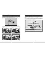
• Installation of the main motor heat sink will require that you to temporarily remove the right-hand main motor from
the main frame . This is easily accomplished by removing the two motor mounting screws found on the bottom of
the main frame .
• With the right-hand main motor removed from the frame, you can press the main motor heat sink into place near
the top/end of the left-hand main motor . We recommend that you use Heat Sink Compound (EFLM1913) on any
surfaces of the heat sink that make contact with the motor case to further improve the effectiveness of the heat
sink . The wider end of the heat sink (more fins) must be placed toward the front of the helicopter .
• You can now press the right-hand main motor into place in the heat sink and use the motor mounting screws to
re-install the motor on the main frame . Again, we recommend that you use Heat Sink Compound (EFLM1913) on
any surfaces of the heat sink that make contact with the motor case to further improve the effectiveness of the
heat sink .
The main motor heat sink is now installed and ready for flight .


