39
40
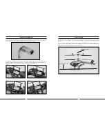
Channel 5 Knob Description and Function
The transmitter included with your Blade CX3 MD 520N is equipped with an optional-use “Channel 5” knob (labeled
as “CH 5”) on the top right panel .
This knob allows you to control function of the transmitter’s 5th channel . This channel remains un-used for flying
the Blade CX3 MD 520N, however, it is available for use in controlling a variety of potential optional features
including actuation of an additional servo or certain electronic components . It allows full proportional control of the
5th channel from approximately 0–100% travel .
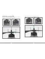
Although no servo reversing is available for this channel, the knob can be operated in either direction for
control. You can use either the most clockwise (+) or most counterclockwise (-) position for 0 or 100% travel,
and you will achieve approximately 50% travel with the knob in the middle position, pointing directly to the rear of
the transmitter .
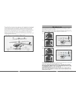
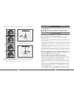
0% (or 100%) Travel
50% Travel
100% (or 0%) Travel
Transmitter and Receiver Binding and Fail-Safe
Binding is the process of programming the receiver to recognize the GUID (Globally Unique Identifier) code of a
single specific transmitter . If you ever find that it is necessary to replace your transmitter or the AR6100e in your
model, it will be necessary for you to “Bind” the new transmitter AR6100e receiver to your existing transmitter or
receiver for proper operation .
During the binding process, the smart fail-safe (SmartSafe
™
) positions of your system are also set . With SmartSafe,
in case of loss of signal, the throttle will go to the preset position that was stored during the binding process and
all other channels will hold their last position . And if the receiver (AR6100e) is powered on before the transmitter, all
channels but throttle will go to the fail-safe positions that were stored during the binding process, while the throttle
channel will not generate a pulse in order to prevent the ESC(s) from arming .
Note: Because the SmartSafe positions are set during the binding process, it is important to set all channels to the
preferred fail-safe positions before proceeding . In the case of the Blade CX3 MD 520N, we strongly recommend
setting the throttle stick and throttle trim to their lowest positions, and the rudder, aileron and elevator channels to
their neutral positions . Channel 5 should be set to your preferred position if you have chosen to utilize it .
The following steps outline the binding process:
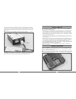
• Each time the transmitter is turned on, it enters “Bind Mode” for a few seconds. You can tell that the transmitter
is in bind mode when you see the red LED located under the door on the bottom left front of the transmitter blink
rapidly . Once the LED becomes solid, the transmitter is no longer in bind mode and will transmit normally .

