User Manual HTS801
Humidity and Temperature Sensor for High Humidity and Chemically Polluted Conditions | 29
4.6
Remote Sensing Probe Type T10
WARNING
General safety instructions for pressure tight installation
The installation, commissioning and operation of the HTS801-T10 may be performed by qualified staff
only. Special attention shall be paid to the correct installation of the probe into the process. In case of
inappropriate installation there is the risk for the probe to be suddenly expulsed due to the pressure in the
process.
Bending over the sensing probe should be avoided under any circumstances!
Make sure that the surface of the probe is not damaged during installation. A damaged probe surface may
lead to damaged seals and consequently to leakage and pressure loss.
The probe is rated with leakage rate B according to EN12266-1.
4.6.1.
Installation of the Probe directly in the Process
NOTICE
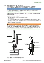
For direct probe installation shut-off valves shall be placed on both sides of the probe insert (see Fig. 30
Installation of the HTS801-T10 probe directly into the process). This allows the sensor probe to be easily
removed for maintenance and calibration.
For direct installation into a pressure chamber make sure that the pressure in the chamber and the ambient
pressure are equal before removing the probe. The temperature during probe installation may deviate by
max. ±40 °C (±72 °F) from the regular temperature during normal operation.
Replace the metal sealing ring (see Fig. 30 ) by a new one every time before re-installing the probe.
Probe installation steps
1.
Close both shut-off valves.
2.
Place the sensor probe into the probe insert and adjust the immersion depth.
3.
Tighten the lock nut with a torque of 30 Nm.
4.
Open the shut-off valves.
WARNING
Observe strictly the tightening torque. A torque lower than 30 Nm results in a smaller retention force of the
clamping sleeve. This leads the risk of sudden expulsion of the sensing probe due to the pressure. A torque
higher than 30 Nm may lead to permanent deformation of the clamping sleeve and the sensing probe. This
would make the removal and re-installation of the probe difficult or even impossible.
Fixed installation (pressure tight up
to 20 bar (300 psi))
Stop valve
1/2".ISO.or.1/2".NPT
Inside diameter
≥
13 mm (0.55")
Metal sealing ring
Fig. 30 Installation of the HTS801-T10 probe directly into the process


