D 40.12 21
1.4
Starting for paving
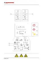
Set the switches, levers and
controls listed below to the specified positions
when the
screed has reached its operating temperature and a sufficient amount of material lies
in front of the screed
- Press the safety switch (13).
- Push the drive lever (1) all the way to the front and start driving.
- Observe the distribution of the material and adjust the limit switches if necessary.
- Set the compacting elements (tamper and/or vibration) according to the required
compaction ratio.
- Let the paving master check the paving thickness after 5–6 meters and correct
if necessary.
Check the area of the caterpillar chains as uneven ground is levelled by the screed.
The caterpillar chains act as reference points for the layer thickness.
The basic setting of the screed must be corrected when the actual layer thickness de-
viates significantly from the values indicated by the scales (see the operating instruc-
tions for the screed).
A
The basic setting is for asphalt material.
Item
Switch
Position
1
Drive lever
Centre position
2
Travel drive fast / slow
Slow ("tortoise")
3
Travel drive preselector
Mark 6-7
4
Engine speed
Maximum
5
Screed position
Floating position
6
Vibration Auto
7
Tamper Auto
8
Auger left/right
Auto
9
Conveyor
Auto
10
Levelling Auto
11
Speed control for the tamper
adapted to the paving situation
12
Speed regulator, vibration
adapted to the paving situation
Summary of Contents for F1250CS
Page 1: ...OPERATION MAINTENANCE Paver Finisher F1250CS Type 458 01 1019 4812076240 ...
Page 2: ...www dynapac com ...
Page 24: ...A 2 ...
Page 31: ...B 7 4 Safety devices 4 5 6 8 2 3 11 9 2 10 1 7 ...
Page 34: ...B 10 5 2 Permissible approach angle max 14 max 12 8 ...
Page 40: ...B 16 8 6 3 5 7 41 14 10 20 15 19 3 6 8 14 18 17 16 21 13 11 5 4 14 12 1 40 2 42 o 10 9 9 ...
Page 41: ...B 17 xxxxxxxxxxxxxxxxx 32 30 31 ...
Page 46: ...B 22 6 3 CE marking No Pictogram Meaning 30 CE sound output level ...
Page 80: ...C 10 12 28 ...
Page 84: ...D 10 12 4 15 16 18 13 19 12 17 14 11 10 10 ...
Page 86: ...D 10 12 6 15 16 18 13 19 12 17 11 10 10 14 ...
Page 88: ...D 10 12 8 15 16 18 13 19 12 17 11 10 10 14 ...
Page 90: ...D 10 12 10 22 21 20 ...
Page 92: ...D 10 12 12 25 24 ...
Page 94: ...D 10 12 14 27 26 ...
Page 96: ...D 10 12 16 29 28 ...
Page 98: ...D 10 12 18 31 ...
Page 100: ...D 10 12 20 32 33 ...
Page 102: ...D 10 12 22 34 ...
Page 104: ...D 10 12 24 36 ...
Page 106: ...D 10 12 26 34 34a ...
Page 108: ...D 10 12 28 35 35a ...
Page 110: ...D 10 12 30 36 38 37 ...
Page 112: ...D 10 12 32 39 ...
Page 114: ...D 10 12 34 41 40 43 42 ...
Page 116: ...D 10 12 36 44 ...
Page 118: ...D 10 12 38 45 ...
Page 120: ...D 10 12 40 46 ...
Page 122: ...D 10 12 42 Electric heating element o 50 51 52 53 ...
Page 124: ...D 10 12 44 Gas heating element o 62 60 61 63 ...
Page 128: ...D 10 12 48 90 91 92 93 94 ...
Page 130: ...D 10 12 50 90 91 92 93 94 ...
Page 136: ...D 10 12 56 4 3 Establish radio link 100 110 41 14 ...
Page 140: ...D 10 12 60 4 5 Control elements of radio remote control 101 100 ...
Page 142: ...D 10 12 62 102 103 ...
Page 144: ...D 10 12 64 106 104 105 109 110 111 107 108 ...
Page 146: ...D 10 12 66 106 104 105 109 110 111 107 108 ...
Page 148: ...D 10 12 68 112 113 114 115 116 ...
Page 150: ...D 10 12 70 112 113 114 115 116 ...
Page 152: ...D 10 12 72 112 113 114 115 116 ...
Page 154: ...D 10 12 74 112 113 114 115 116 ...
Page 156: ...D 10 12 76 121 122 123 124 117 118 119 120 ...
Page 158: ...D 10 12 78 121 122 123 124 117 118 119 120 ...
Page 160: ...D 10 12 80 121 122 123 124 117 118 119 120 ...
Page 163: ...D 24 12 1 D 24 12 Operating the display ...
Page 188: ...D 24 12 26 Example ...
Page 210: ...D 30 12 20 ...
Page 215: ...D 40 12 5 1 5 2 5 5 4 6 3 9 7 8 ...
Page 217: ...D 40 12 7 1 5 2 5 5 4 6 3 9 7 8 ...
Page 220: ...D 40 12 10 5 4 5 5 1 2 3 ...
Page 222: ...D 40 12 12 6 2 1 3 4 4 4 5 5 5 7 ...
Page 224: ...D 40 12 14 4 6 2 6 6 1 3 5 ...
Page 228: ...D 40 12 18 2 2 1 2 3 4 ...
Page 230: ...D 40 12 20 1 3 8 8 2 13 4 5 6 7 8 9 12 11 10 ...
Page 233: ...D 40 12 23 1 2 3 4 5 ...
Page 235: ...D 40 12 25 1 2 4 4 16 3 9 7 6 4 5 8 11 11 10 12 13 14 11 10 10 17 15 ...
Page 252: ...E 10 12 10 ...
Page 257: ...F 3 12 1 F 3 12 Maintenance conveyor 1 Maintenance conveyor ...
Page 264: ...F 3 12 8 ...
Page 265: ...F 4 12 1 F 4 12 Maintenance auger assembly 1 Maintenance auger assembly ...
Page 288: ...F 5 12 16 ...
Page 289: ...F 6 12 1 F 6 12 Maintenance hydraulic system 1 Maintenance hydraulic system ...
Page 303: ...F 7 12 1 F 7 12 Maintenance drive unit 1 Maintenance drive unit ...
Page 313: ...F 8 12 1 F 8 12 Maintenance electrical system 1 Maintenance electrical system ...
Page 328: ...F 11 12 2 7 1 5 6 6 4 2 8 3 ...
Page 334: ...F 11 12 8 ...
Page 335: ...F 100 1 F 100 Checking shutdown 1 Tests checks cleaning shutdown and disposal ...
Page 347: ......
Page 348: ...www dynapac com ...


