D 10.12 5
Item Designation
Brief description
10
Lights
Lights up instrument panel A/B when the parking light is
switched on
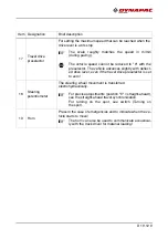
11
Emergency stop
button
Press in an emergency (danger to persons, impending colli-
sion, etc.)!
-
Pressing the emergency stop button switches off the en-
gine, the drives and the steering system.
Making way, lifting the screed or other actions are then no
longer possible! Danger of accident!
-
The emergency stop button does not shut off the gas heat-
er system.
Close the main shut-off valve and the valves on the bottles
by hand!
-
To restart the engine, the button must be unlocked again.
12
Engine speed
adjuster
Continuously variable engine speed setting
(if drive lever is extended).
Min. setting: Idling speed
Max. position: Nominal speed
A
For paving, select the rated speed; reduce the speed
for transportation.
A
The automatic speed control keeps the set speed con-
stant even under a load.
13
Straight-
ahead travel
synchronisation
Using this potentiometer, both chains can be synchronised for
straight-ahead travel while driving:
-
Set the steering to position "0"; then adjust the potentiom-
eter until the paver finisher is travelling straight ahead.
14
Ignition lock
Switch positions:
-
P: Park po warning lamps can be engaged when
desired.
-
0: Ignition OFF
-
1: Ignition ON, lighting and separator fluid spray system
can be activated.
- 2: Starter function
A
The engine can only start up if the drive lever is in the
middle setting and no "AUTO" or "MANUAL" functions
are switched on.
A
Removal of the key is only possible in position 0.
Summary of Contents for F1250CS
Page 1: ...OPERATION MAINTENANCE Paver Finisher F1250CS Type 458 01 1019 4812076240 ...
Page 2: ...www dynapac com ...
Page 24: ...A 2 ...
Page 31: ...B 7 4 Safety devices 4 5 6 8 2 3 11 9 2 10 1 7 ...
Page 34: ...B 10 5 2 Permissible approach angle max 14 max 12 8 ...
Page 40: ...B 16 8 6 3 5 7 41 14 10 20 15 19 3 6 8 14 18 17 16 21 13 11 5 4 14 12 1 40 2 42 o 10 9 9 ...
Page 41: ...B 17 xxxxxxxxxxxxxxxxx 32 30 31 ...
Page 46: ...B 22 6 3 CE marking No Pictogram Meaning 30 CE sound output level ...
Page 80: ...C 10 12 28 ...
Page 84: ...D 10 12 4 15 16 18 13 19 12 17 14 11 10 10 ...
Page 86: ...D 10 12 6 15 16 18 13 19 12 17 11 10 10 14 ...
Page 88: ...D 10 12 8 15 16 18 13 19 12 17 11 10 10 14 ...
Page 90: ...D 10 12 10 22 21 20 ...
Page 92: ...D 10 12 12 25 24 ...
Page 94: ...D 10 12 14 27 26 ...
Page 96: ...D 10 12 16 29 28 ...
Page 98: ...D 10 12 18 31 ...
Page 100: ...D 10 12 20 32 33 ...
Page 102: ...D 10 12 22 34 ...
Page 104: ...D 10 12 24 36 ...
Page 106: ...D 10 12 26 34 34a ...
Page 108: ...D 10 12 28 35 35a ...
Page 110: ...D 10 12 30 36 38 37 ...
Page 112: ...D 10 12 32 39 ...
Page 114: ...D 10 12 34 41 40 43 42 ...
Page 116: ...D 10 12 36 44 ...
Page 118: ...D 10 12 38 45 ...
Page 120: ...D 10 12 40 46 ...
Page 122: ...D 10 12 42 Electric heating element o 50 51 52 53 ...
Page 124: ...D 10 12 44 Gas heating element o 62 60 61 63 ...
Page 128: ...D 10 12 48 90 91 92 93 94 ...
Page 130: ...D 10 12 50 90 91 92 93 94 ...
Page 136: ...D 10 12 56 4 3 Establish radio link 100 110 41 14 ...
Page 140: ...D 10 12 60 4 5 Control elements of radio remote control 101 100 ...
Page 142: ...D 10 12 62 102 103 ...
Page 144: ...D 10 12 64 106 104 105 109 110 111 107 108 ...
Page 146: ...D 10 12 66 106 104 105 109 110 111 107 108 ...
Page 148: ...D 10 12 68 112 113 114 115 116 ...
Page 150: ...D 10 12 70 112 113 114 115 116 ...
Page 152: ...D 10 12 72 112 113 114 115 116 ...
Page 154: ...D 10 12 74 112 113 114 115 116 ...
Page 156: ...D 10 12 76 121 122 123 124 117 118 119 120 ...
Page 158: ...D 10 12 78 121 122 123 124 117 118 119 120 ...
Page 160: ...D 10 12 80 121 122 123 124 117 118 119 120 ...
Page 163: ...D 24 12 1 D 24 12 Operating the display ...
Page 188: ...D 24 12 26 Example ...
Page 210: ...D 30 12 20 ...
Page 215: ...D 40 12 5 1 5 2 5 5 4 6 3 9 7 8 ...
Page 217: ...D 40 12 7 1 5 2 5 5 4 6 3 9 7 8 ...
Page 220: ...D 40 12 10 5 4 5 5 1 2 3 ...
Page 222: ...D 40 12 12 6 2 1 3 4 4 4 5 5 5 7 ...
Page 224: ...D 40 12 14 4 6 2 6 6 1 3 5 ...
Page 228: ...D 40 12 18 2 2 1 2 3 4 ...
Page 230: ...D 40 12 20 1 3 8 8 2 13 4 5 6 7 8 9 12 11 10 ...
Page 233: ...D 40 12 23 1 2 3 4 5 ...
Page 235: ...D 40 12 25 1 2 4 4 16 3 9 7 6 4 5 8 11 11 10 12 13 14 11 10 10 17 15 ...
Page 252: ...E 10 12 10 ...
Page 257: ...F 3 12 1 F 3 12 Maintenance conveyor 1 Maintenance conveyor ...
Page 264: ...F 3 12 8 ...
Page 265: ...F 4 12 1 F 4 12 Maintenance auger assembly 1 Maintenance auger assembly ...
Page 288: ...F 5 12 16 ...
Page 289: ...F 6 12 1 F 6 12 Maintenance hydraulic system 1 Maintenance hydraulic system ...
Page 303: ...F 7 12 1 F 7 12 Maintenance drive unit 1 Maintenance drive unit ...
Page 313: ...F 8 12 1 F 8 12 Maintenance electrical system 1 Maintenance electrical system ...
Page 328: ...F 11 12 2 7 1 5 6 6 4 2 8 3 ...
Page 334: ...F 11 12 8 ...
Page 335: ...F 100 1 F 100 Checking shutdown 1 Tests checks cleaning shutdown and disposal ...
Page 347: ......
Page 348: ...www dynapac com ...


