background image

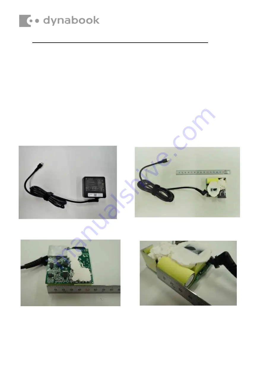
AC Adapter, External cables provided with the AC adapter and USB cables 

The AC adapter as well as all external cables provided with the notebook including the AC adapter cables 

and USB cables should be segregated and sent for shredding. 

The following components contained within the AC adapter potentially contain hazardous substances and 

require special handling: 

Printed Circuit Board >10 cm

2

Capacitor >25 mm in height

Photos of the AC adapter and the components noted above are included below. 

The notebook has one of two types of AC adapter. 

USB connection type 

AC adapter 

AC Adapter with casing removed 

AC Adapter printed circuit board 

AC adapter capacitor 

Summary of Contents for Satellite C50-K

Page 1: ...l For your safety and that of other people in the working environment it is strongly recommended that you use electrostatic discharge ESD equipment The proper use of this equipment will ensure successful repair work and reduce the costs for repairing damaged components The equipment and tools required for disassembly and reassembly are One 2 mm Phillips screwdriver One 4 mm flat blade screwdriver ...

Page 2: ...r local requirements To remove the battery the base assembly must be removed first 4 2 Base cover Removing the base cover Remove the base cover according to the following procedures and Figure4 1 1 Turn the laptop upside down so that the bottom is facing up 2 Remove the six M2x5 screws 1 This four screws have angle to fix D cover 3 Press the cover edge and pry up the base cover from the inner edge...

Page 3: ... Figure4 2 1 Detach the Battery connector 1 2 Remove the four M2x3 screws 2 3 Remove the battery pack 3 Figure4 2 Removing the Battery Pack CAUTION When handling the battery pack use cares not to short circuit the terminals Do not drop hit twist or bend the battery pack Do not scratch or break up their casing ...

Page 4: ...ing the SSD Card Remove the SSD Card WLAN Card DIMM assembly according to the following procedures and Figure4 7 1 Remove the one M2x3 screw and SSD card from the motherboard 3 4 Figure4 7 Removing the SSD Card WLAN Card DIMM ...

Page 5: ...B PWB system board Beside the LCD and the main PCB there are further small PCBs and components which are in the scope of the WEEE Directive The removal of these components is described in detail in the chapter 4 of the associated maintenance manual ...

Page 6: ...4 8 Figure4 13 Removing the Motherboard 4 9 Figure4 14 Removing the Touch Pad Module 4 10 Figure4 15 Removing the Touch Pad Module 4 11 Figure4 16 Location of Electronic tape Conductive tape 4 11 Figure4 17 W LAN edp Cables Routing Channel 4 12 Figure4 18 Removing the LCD Assembly 4 13 Figure4 19 Removing the Bezel 4 14 Figure4 20 Removing the Panel Adhesive 4 14 Figure4 21 Removing the Panel Asse...

Page 7: ...m is facing up 2 Remove the six M2x5 screws 1 This four screws have angle to fix D cover 3 Press the cover edge and pry up the base cover from the inner edges starting from the top 2 then along the sides 3 and then the bottom 4 4 Slightly shake the base cover to release the center snap on base cover 5 5 Remove the base cover 6 Figure4 1 Removing the Base Cover ...

Page 8: ...over with the snaps on the logic upper assembly and gently press downward the edges of the base cover until clicks are heard Make sure all the snaps are latched and secured 2 Tighten the ten M2 5 screws 1 the four screws have angles to secure the base cover to the logic upper assembly as shown in Figure4 1 ...

Page 9: ... Figure4 2 1 Detach the Battery connector 1 2 Remove the four M2x3 screws 2 3 Remove the battery pack 3 Figure4 2 Removing the Battery Pack CAUTION When handling the battery pack use cares not to short circuit the terminals Do not drop hit twist or bend the battery pack Do not scratch or break up their casing ...

Page 10: ...y pack according to the following procedures 1 Seat the battery pack in the correct position on the logic upper assembly and insert the battery connector 1 3 2 Tighten the four M2 x 3 screws to secure the battery pack to the logic upper assembly 2 ...

Page 11: ... the following procedures and Figure4 3 Figure4 4 1 Peel off the W LAN Mylar securing the cable connector in place 6 and disconnect the two W LAN antennas White Black color from motherboard 7 as shown in Figure4 4 2 Gently pull up the W LAN antennas out of the routing channels on fan 8 3 Disconnect the Fan cable from the motherboard 1 4 Remove the two M2x3 screws and fan 2 Remove the three M2x3 sc...

Page 12: ...Figure4 3 Removing the Fan and thermal module Figure4 4 Removing the w lan cable ...

Page 13: ...embly as show in Figure4 3 3 Check the greasy is attached on the thermal module as shown in Figure4 6 4 Place the thermal module in the correct position on the motherboard 5 Tighten the three M2 x 3 screws according to the number sequence 3 4 5 indicated in Figure4 3 to secure the thermal module to the motherboard 6 For the w lan cable routing tuck the w lan cable into the fan hook 11 and wlan cab...

Page 14: ...Figure4 6 Checking the Thermal Pad on Thermal module ...

Page 15: ...assembly according to the following procedures and Figure4 7 1 Remove the one M2x3 screw and Wlan card from the motherboard 1 2 2 Remove the one M2x3 screw and SSD card from the motherboard 3 4 3 Remove the DDR shielding and DIMM from the motherboard 5 6 Figure4 7 Removing the SSD Card WLAN Card DIMM ...

Page 16: ...lan in the correct position and tighten the one M2 x 3 screw to secure the wlan to the motherboard assembly 1 2 2 Seat the SSD in the correct position and tighten the one M2 x 3 screw to secure the wlan to the motherboard assembly 3 4 3 Seat the DIMM in the correct position and seat the shielding cover to the motherboard 5 6 ...

Page 17: ...e speaker assembly according to the following procedures and Figure4 8 Disconnect the speaker cable from the motherboard 1 1 Gently pull up the speaker assembly and the speaker cable out of the routing channels 2 3 Figure4 8 Removing the Speakers ...

Page 18: ...y 3 as shown in Figure4 8 2 Route and secure the speaker cable in the routing channels as shown in Figure4 9 3 Connect the speaker cable to the motherboard 1 as shown in Figure4 8 Figure4 9 Speaker Cable routing channels on upper NOTE Take care not to pinch the cables Make sure the routing positions of the cables are correct and do not block any components such as screw holes ...

Page 19: ...IO board according to the following procedures and Figure4 10 1 Disconnect the IO board FFC 1 2 2 Remove one M2x3 screw 3 3 Gently lift up the right edge of the IO board and remove it from the logic upper assembly 4 Figure4 10 Removing the IO Board ...

Page 20: ...ng procedures 1 Seat the IO board in the correct position on the logic upper assembly 4 2 Tighten one M2 3 screw to secure the IO board to the logic upper assembly 3 3 Connect the IO board FFC to the IO board Make sure the FFC are properly engaged and firmly secured 1 2 ...

Page 21: ...rd Remove the Sensor board according to the following procedures and Figure4 11 1 Disconnect the sensor board FFC 1 2 2 Gently pry up the sensor board from the adhesive and remove it from the Upper cover 3 Figure4 11 Removing the sensor board ...

Page 22: ...t the sensor board in the correct position and secure it in place with adhesives on the upper cover as shown in Figure4 12 2 Connect the sensor board FFC to the sensor board Make sure the FFC are properly engaged and firmly secured 1 2 Figure4 12 Removing the release paper of sensor board adhesive ...

Page 23: ...ing the motherboard to the logic upper assembly 2 Disconnect the eDP cable 2 DCIN cable 3 sensor board FFC 4 5 TP FFC 6 7 keyboard FPC 8 9 IO FFC 10 11 FP FFC 12 13 from the motherboard as shown in Figure4 13 3 Gently lift the left edge of the motherboard and remove the motherboard from the logic upper assembly 14 Figure4 13 Removing the Motherboard ...

Page 24: ... upper assembly 2 Tighten four M2 3 screw 1 to secure the motherboard to logic upper assembly as shown in Figure4 13 3 Connect the eDP cable 2 DCIN cable 3 sensor board FFC 4 5 TP FFC 6 7 keyboard FPC 8 9 IO FFC 10 11 FP FFC 12 13 to the motherboard as shown in Figure4 13 Make sure the FPC and the connectors are properly engaged and firmly secured ...

Page 25: ...and Figure4 14 1 Disconnect the finger print FFC from finger print module 1 2 2 Remove the one M2 2 screw securing the finger print bracket to the logic upper assembly 3 3 Remove finger print bracket 4 from the logic upper 4 Gently push the finger print away from the logic upper assembly 5 Figure4 14 Removing the Touch Pad Module ...

Page 26: ...procedures 1 Seat the finger print in the correct position on the logic upper assembly 5 2 Place the finger print bracket on the logic upper assembly 4 3 Tighten one M2 2 screw to secure the finger print bracket to the logic upper assembly 3 4 Connect the finger print FFC to the finger print 1 2 ...

Page 27: ...the touch pad FFC from touch pad module 1 2 2 Peel away the conductive tape 6 on logic upper assembly from touch pad 3 Remove the two M2 3 screws securing the tp support bracket to the logic upper assembly 3 4 Remove tp support bracket 4 from the logic upper 5 Gently push the touch pad away from the logic upper assembly 5 Figure4 15 Removing the Touch Pad Module ...

Page 28: ... in the correct position on the logic upper assembly 5 2 Seat the TP support bracket in the correct position on the logic upper assembly 4 and tighten two M2 3 screws to secure the tp support bracket to the logic upper assembly 3 3 Connect the touch pad FPC to the touch pad 1 2 4 Adhere the conductive tape over the touch pad and logic upper assembly as shown in Figure4 16 6 ...

Page 29: ... cable out of the routing channels as shown in Figure4 17 1 2 2 Remove the four M2 5x5 screws 3 securing the LCD assembly as shown in Figure4 18 3 Make sure all cables are moved away from the logic upper assembly to avoid damaging the system when removing the LCD assembly Lift away the LCD assembly from the logic upper assembly as the arrow 4 indicates in Figure4 18 ...

Page 30: ...Figure4 17 W LAN edp Cables Routing Channel Figure4 18 Removing the LCD Assembly ...

Page 31: ...180 degree angle and seat the LCD assembly in the correct position on the logic upper assembly and the cables must be placed inside the hook of hinge bracket 4 3 Tighten the six M2 5 5 screws to secure the LCD assembly to the logic upper assembly as shown inFigure4 18 3 4 Route and secure the W LAN cables and edp cable in the routing channels on the logic upper assembly as shown in Figure4 17 2 1 ...

Page 32: ...Figure4 19 1 Place the LCD assembly right side up so that the top is facing up 2 Insert a smooth flat instrument into the gap between the Bezel and the LCD cover as shown in Figure4 19 and then gently twist the instrument to pry up the Bezel from the LCD cover Figure4 19 Removing the Bezel ...

Page 33: ...ing procedures 1 Place the Bezel on the LCD cover assembly Make sure the tabs on the back of the Bezel align with the slots in the LCD cover assembly 2 Gently press down edges around the Bezel until clicks are heard Make sure all the snaps are latched and secured ...

Page 34: ...wn in Figure4 20 2 Carefully lift up and rotate the panel from the LCD assembly as the arrow 2 indicates in Figure4 21 3 Place the panel on a protective surface such as a foam pad as shown in Figure4 22 4 Disconnect the eDP cable FFC from Camera FPC 3 4 5 and Gently pry up the Camera FPC 6 as shown in Figure4 22 5 Pull the lock bar outward and disconnect the eDP cable from the touch glass panel 7 ...

Page 35: ...Figure4 20 Removing the Panel Adhesive Figure4 21 Removing the Panel Assembly ...

Page 36: ...Figure4 22 Disconnecting the eDP Cables FFC from Camera FPC Assembly Figure4 23 Disconnecting the Cables from Panel Assembly ...

Page 37: ... with lock bar then adhere the mylar over the connector to secure it in place as shown in Figure4 23 7 8 3 Connect the eDP cable FFC to the camera FPC board connector as shown inFigure4 22 6 5 4 3 4 Pull up the blue release paper of Panel Adesive from LCD coveras show in Figure4 25 2 5 Rotate the panel right side up and use 0 5mm Mylar between LCD cover and Panel to seat it in the correct position...

Page 38: ...Figure4 24 Removing the Release Paper of Panel Adhesive Figure4 25 Panel assembly explanation ...

Page 39: ...nd remove it from the LCD cover 2 3 Removing the Antenna module from the adhesive and remove it from the LCD cover 3 4 Removing the Antenna module cable from the LCD cover 4 5 5 Gently pry up the Cu Foil from the adhesive and remove it from the LCD cover 6 6 Removing the Antenna module from the adhesive and remove it from the LCD cover 7 Figure4 26 Removing the Antenna module NOTE Antenna module i...

Page 40: ...ehind it 7 2 Pasting the Cu Foil_A in the correct position 6 3 Seat the Antenna cable in the correct position and secure it in place 4 5 4 Seat the Antenna module_B in the correct position and secure it in place with adhesives behind it 3 5 Pasting the Cu Foil_B in the correct position 2 6 Seat the Antenna cable in the correct position and secure it in place with adhesives behind it 1 ...

Page 41: ...rom the LCD cover 1 Camera module is fixed by adhesive on the LCD cover Figure4 27 Removing the Camera Module Installing the Camera Module Install the camera module according to the following procedure Seat the camera module in the correct position and secure it in place with adhesives behind it 1 NOTE Camera module is fastened by adhesives Remove it slowly and carefully ...

Page 42: ... LCD Hinges Remove the LCD hinges according to the following procedures and Figure4 28 1 Remove the six M2 2 5 screws securing the LCD hinges 1 2 Remove the two M2 3 screws securing the LCD hinges 2 Figure4 28 Removing LCD Hinges ...

Page 43: ...stall the LCD hinges according to the following procedures 1 Tighten the six M2 2 5 screws to secure the LCD hinges to the hinge cover assembly 1 2 Tighten the two M2 3 screws to secure the LCD hinges to the hinge cover assembly 2 ...

Page 44: ...e4 27 4 Seat and adhere the Antenna module in the correct position on the LCD cover assembly as shown in Figure4 26 5 Place the panel assembly upside down so that the bottom is facing up 6 Connect the eDP cable to the panel connector and lock it with lock bar then adhere the mylar over the connector to secure it in place as shown in Figure4 23 7 Connect the eDP cable FFC to the camera FPC board co...

Page 45: ...redding The following components contained within the AC adapter potentially contain hazardous substances and require special handling Printed Circuit Board 10 cm2 Capacitor 25 mm in height Photos of the AC adapter and the components noted above are included below The notebook has one of two types of AC adapter USB connection type AC adapter AC Adapter with casing removed AC Adapter printed circui...

Page 46: ...Conventional type AC adapter AC Adapter with casing removed AC adapter printed circuit board AC adapter capacitor ...

Reviews: