background image

4-3

SpycerBox Ultra/Flex | Hardware Guide | Version 3.1

Rohde & Schwarz DVS GmbH

Operation



DVS Configuration Tool

4.2  DVS Configuration Tool

Depending on the system, it is either delivered with the DVS Configu-
ration Tool or SAN Remo (see section “R&S DVS SAN Remo” on 
page 4-4) as standard. T
he DVS Configuration Tool can be used to con-
figure, reboot and shut down the SpycerBox. Once the operating sys-
tem is loaded, it can be found on the desktop of the SpycerBox.

The DVS Configuration Tool will run in the standard web browser of 
your system. The address is either 

localhost

 (

127.0.0.1

) or the IP 

address of the SpycerBox in the network. After starting it you have to 
enter a user name (default: 

admin

) and password (default: 

dvssan

).

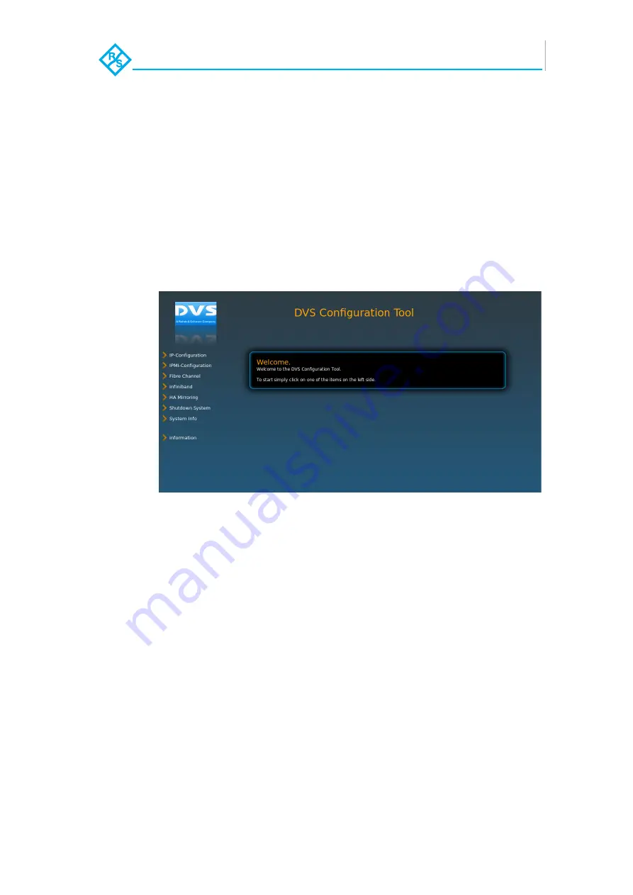
Figure 4-2: Starting screen of the DVS Configuration Tool

With the DVS Configuration Tool you can change the configurations of 
the R&S DVS system (e.g. its IP address or Fibre Channel connections). 
Click on the respective item to the left to view and change the config-
urations. Afterwards you will see the options that can be changed.

The DVS Configuration Tool can also be used to gather log files of the 
system, for example, for troubleshooting. By default they will be saved 
in a single archive file on the desktop of your system.

Additionally, with the DVS Configuration Tool you can reboot or shut 
down the R&S DVS system.

Summary of Contents for SpycerBox Flex

Page 1: ...SpycerBox Ultra Flex Hardware Guide Version 3 1 Storage Solution SpycerBox Ultra Flex Hardware Guide...

Page 2: ...SpycerBox Ultra Flex Hardware Guide Version 3 1 Rohde Schwarz DVS GmbH...

Page 3: ...no guarantee that this documentation is correct and or complete In no event shall Rohde Schwarz DVS GmbH be liable for any damages whatsoever including without limitation any special indirect or conse...

Page 4: ...VS GmbH Headquarters Support Rohde Schwarz DVS GmbH Krepenstr 8 30165 Hannover GERMANY Phone 49 511 67807 0 Fax 49 511 630070 E mail info dvs rohde schwarz com Internet http www dvs de Phone 49 511 67...

Page 5: ...urs please fill in this registration form and send or fax it to the address on the right You may also use our online registration form which can be accessed from the following internet page http www d...

Page 6: ...SpycerBox Ultra Flex Hardware Guide Version 3 1 Rohde Schwarz DVS GmbH...

Page 7: ...nd SpycerBox Flex 2 2 2 2 Overview of the Front 2 2 2 2 1 The Front of the System 2 2 2 2 2 DVD Drive 2 4 2 2 3 HDD LEDs 2 4 2 2 4 Faceplate 2 6 2 2 5 Hard Disk Array 2 7 2 2 6 Operation Items 2 9 2 3...

Page 8: ...g 5 8 5 2 2 Closing the Casing 5 9 5 3 Fan Maintenance 5 9 5 4 Controller Maintenance 5 12 5 5 Power Supply Maintenance 5 15 5 6 Backup or Recovery of the System Disk 5 17 5 6 1 Creating a Backup Imag...

Page 9: ...rBox software an extended version of R S DVS s data manage ment software Spycer With the SpycerBox software you can for in stance automatically create low resolution proxy video clips of the content o...

Page 10: ...important notes that you should observe Chapter 2 This chapter gives a front and rear overview of the system detailing all items connectors and interfaces Additionally it contains some further inform...

Page 11: ...ment Furthermore to connect the R S DVS system to a network or a SAN storage you should have experience as a network administrator and know how to set up the required network connections on the in sta...

Page 12: ...k and help avoid errors Cause of Risk Indicates the possibility of incorrect operation which can result in damage to the product You must pay particular attention to text that follows this symbol to a...

Page 13: ...and quoted labelings Window Text in bold with single quotation marks indi cates a window name BUTTON Text in small caps and bold indicates a push but ton Group Menu Text in italic and bold indicates e...

Page 14: ...a wrist strap connected to ground when accessing electronic parts and take care of grounding the system Avoid touching the internal components of the R S DVS system whenever possible Computer hardware...

Page 15: ...oid shocks or vibrations during transport For longer distances it is recommended to use a lifting truck Keep the R S DVS system as a transportation good dry In the warranty period you have to keep the...

Page 16: ...ess for the necessary repairs to be performed In the warran ty period the customer must keep the original packing and pack the R S DVS product in it in case of a product return If the customer is not...

Page 17: ...the de vice free of charge to a waste disposal organization which will recycle and reuse it environmental friendly General Notes Please observe the following general important notes Performance losses...

Page 18: ...Introduction Important Notes 1 10 SpycerBox Ultra Flex Hardware Guide Version 3 1 Rohde Schwarz DVS GmbH...

Page 19: ...overview of the hardware of the R S DVS system First the different hardware variants of system will be ex plained After this it will be shown in a front and a rear view and all its parts and connecto...

Page 20: ...d disk array where the hard disks are installed see section Hard Disk Array on page 2 7 the two variants are in most re spects identical Whereever required the specialities of these variants will be d...

Page 21: ...of the hard disks for example to replace it it can be lifted The faceplate will be described in more detail in section Faceplate on page 2 6 The hard disk array contains the main storage hard disks w...

Page 22: ...LEDs show the statuses activities of the hard disks of the hard disk array see section Hard Disk Array on page 2 7 They can be seen only when they are flashing because they are located behind the whi...

Page 23: ...sks of the hard disk array is displayed by one LED Figure 2 5 HDD LEDs and the hard disk array SpycerBox Flex Starting from the left the first eight LEDs display the accesses to the hard disks in the...

Page 24: ...the R S DVS logo is illuminated the power is turned on if not the power is turned off The top side of the faceplate is hinge fastened while its bottom side is fixed with magnets If you need access to...

Page 25: ...age of the R S DVS system To prevent data loss in case a hard disk fails it is normally RAID protect ed Once the faceplate is lifted see section Faceplate on page 2 6 you have access to the hard disk...

Page 26: ...failure Figure 2 9 Hard disk carrier overview SpycerBox Ultra and SpycerBox Flex The hinge wires hold the faceplate in place and allow you to lift it For further information see section Faceplate on p...

Page 27: ...Once the lever is unlatched with the opener it can be used to pull the disk carrier and its hard disk out of the system opener Unlatches the lever and with it the disk carrier LED disk power Shows wh...

Page 28: ...n pointed object to press this button Some alarms e g the one in case of a hard disk failure are independent of the system alarm and cannot be switched mute with the mute button 6 reset Resets your sy...

Page 29: ...system disk array The system disk array contains the hard disks for the operating system and metadata You can find further information about this in sec tion System Disk Array on page 2 12 ATX connect...

Page 30: ...rd disk easy for exam ple in the event of a failure The system disk array is equipped with the same type of disk carriers as used in the hard disk array of the Spycer Box Flex see section Hard Disk Ar...

Page 31: ...system holds the connectors of the computer system It provides the following connec tions Figure 2 13 ATX connector panel on rear of the SpycerBox Ultra Figure 2 14 ATX connector panel on rear of the...

Page 32: ...wait several min utes before the configuration takes effect 4 CEN LFE Connector for center out and subwoofer speakers 5 line in Connector to input audio signals 6 keyboard PS 2 connector to connect a...

Page 33: ...nes 14 mike Connector to input low level audio signals System down in case of second power supply failure The system can be operated with one power supply unit out of or der However if another one fai...

Page 34: ...a SAN The following figure shows an example configuration of the slot panel connector area Figure 2 16 Example of a slot panel configuration on the SpycerBox Ultra latch The latch of a power supply u...

Page 35: ...our request The slot panels showing Option in the figures above represent empty slot panels for optional cards that you can order To provide connections to most networks there are various interface po...

Page 36: ...in the delivery of the system SAS The SAS serial attached SCSI connector is an external mini SAS SFF 8088 connector that can be used to connect external storages In some cases the slot panel may provi...

Page 37: ...ovide power to the cache of the connected RAID controller so that buffered data will not get lost Once the operation of the system is restored the cached data will be written to the hard disks The bat...

Page 38: ...Overview Battery Backup Unit 2 20 SpycerBox Ultra Flex Hardware Guide Version 3 1 Rohde Schwarz DVS GmbH...

Page 39: ...air circulation and cooling make sure the ventilation holes are not covered 3 Connect at least the following computer peripherals Mouse keyboard and a monitor that is operable at a resolution of at le...

Page 40: ...e how to connect the R S DVS system to a network or central storage On the R S DVS web page www dvs de you can find some diagrams showing how the SpycerBox may fit in a workflow network To connect the...

Page 41: ...or both procedures you have to use the power switch of the operation items at the front of the system Figure 4 1 The power switch Additionally the DVS Configuration Tool is described briefly which al...

Page 42: ...ss the power switch briefly to turn on the system The system will be started and the R S DVS logo in the middle of the faceplate lights up As with any standard computer after initial booting the syste...

Page 43: ...27 0 0 1 or the IP address of the SpycerBox in the network After starting it you have to enter a user name default admin and password default dvssan Figure 4 2 Starting screen of the DVS Configuration...

Page 44: ...ter starting it you have to enter a user name default admin and pass word default admin Figure 4 3 Plugin view in the SAN Remo software With SAN Remo you can change the configurations of the R S DVS s...

Page 45: ...DVS SAN Remo on page 4 4 The operating system will then save your personal settings and once it has ended the system will turn off Some settings will be saved and afterwards the system turns off For...

Page 46: ...sponding anymore or not completely loaded perform the following 1 Shut down the system by pressing the power switch until the sys tem turns off The system will then shut down immediately This procedur...

Page 47: ...r explains the maintenance work that you can perform on your own For each work a detailed procedure description is given If you experience trouble with the system that cannot be resolved with the work...

Page 48: ...independently administers the data protection for the set of hard disks that is connected to it The system disk array for the system metadata hard disks comprises four disks They are connected to a R...

Page 49: ...disks represent one disk set RAID pack Figure 5 1 Disk sets RAID packs of the hard disk array SpycerBox Ultra and Flex With the available RAID feature the R S DVS system can withstand disk failures wi...

Page 50: ...leshooting on page A 2 first for further details about what to do in case of an alarm If a hard disk fails the alarm will be sounded by a RAID controller It can not be switched mute with the mute butt...

Page 51: ...remove a hard disk from the system perform the following 1 If appropriate stop all accesses to the hard disks of your system for example by exiting software and severing the network con nections 2 Li...

Page 52: ...he Hard Disk To replace the hard disk do the following 1 Unscrew the screws that fix the hard disk to the disk carrier 2 Exchange the broken disk with a new one and assemble it in the disk carrier wit...

Page 53: ...m is back in place the replace ment of the hard disk is finished After several minutes the replaced hard disk will be automatically recognized by the system Then the re build of the data will be initi...

Page 54: ...wn the System on page 4 5 2 Disconnect all power cords from the system 3 Press the two buttons at the top of the system 1 in the figure below and move the cover towards the rear of the system 2 in the...

Page 55: ...s what to do if a fan failure takes place When a fan failure occurs you will be notified by a lit alarm LED and the sounding of an alarm buzzer of the system The alarm can be switched mute with the mu...

Page 56: ...1 in the figure below 8 With the locking mechanism released pull the fan module up and out of the system 2 in the figure below System damage Computer hardware contains components that are sensitive to...

Page 57: ...n ger protection grille to the fan 11 Re insert the repaired fan module into the system 12 Next close the casing of the system as described in section Clos ing the Casing on page 5 9 With the last ste...

Page 58: ...ables that are connected to it To make this easy the cables are numbered 4 Disconnect the cables connected to the controller System damage Incorrect exchange of the RAID controller can cause damages t...

Page 59: ...trl A to enter Adaptec RAID Configuration Utility Press Ctrl H to Pause Configuration Messages Default i s not to accept if no valid key pressed in 30 seconds 9 Press Enter on the keyboard to accept t...

Page 60: ...the boot device in the BIOS of the RAID To access the RAID BIOS press Ctrl H at the indicated moment during the start up of the system The setting can be found after select ing the respective control...

Page 61: ...nd examine the LEDs of the units The LED of the malfunctioning power supply unit should be extinguished 2 Next unplug the power cord from this power supply unit 3 Unscrew the security screw of the lat...

Page 62: ...Connect the power source power cord to the newly installed power supply unit 10 After that check the LED indicating the status of the power supply unit If it is lit up in green the unit is working pro...

Page 63: ...screen select the inter nally installed USB flash drive as the boot device and then press Enter on your keyboard With this the target device has been selected The system will now boot from the interna...

Page 64: ...ss Enter on your keyboard The system will now ask you to enter the image name for your backup image to be saved By entering the name of an already existing backup image you can overwrite it 7 Type in...

Page 65: ...menu is displayed on the screen select the inter nally installed USB flash drive as the boot device and then press Enter on your keyboard The system will now boot from the internal USB and you will s...

Page 66: ...en detailing the possible source images If there is only the R S DVS recovery image on the USB flash drive this one will be listed If there are several images all will be displayed 7 Select the image...

Page 67: ...the recovery process you will be notified about this Then after pressing Enter on your keyboard you will be re directed to the DVS Rescue script once more where you can choose for example reboot or p...

Page 68: ...R S DVS logo of the faceplate with power 2 Unplug the jack connection 3 Next hold tight the faceplate and remove the hinge wires as indi cated in the following figure Figure 5 5 Removing the hinge wir...

Page 69: ...e Guide Version 3 1 Rohde Schwarz DVS GmbH Appendix Appendix This chapter first gives some hints how to resolve irregularities during operation After that technical data and general information about...

Page 70: ...em If this is not successful con tact the R S DVS service depart ment A RAID controller is defective If you can rule out the above men tioned causes a RAID controller may be defective Before attemptin...

Page 71: ...se a power supply unit has failed Replace the broken unit as described in section Power Supply Mainte nance on page 5 15 A fan has failed Check the LEDs of the power supply units If all are green shut...

Page 72: ...e following Pull all disk carriers partial ly out of the chassis and afterwards install them again See to it that they are pulled out and reassembled cor rectly as described in section Re placing a Ha...

Page 73: ...p ment Measured with SpycerBox Ultra II Revision 1 2 2 EX5650 2 67 GHz 12 GB RAM 24 HUS724030AL 2 HTS725050A7 2 SD6SB2M2 Chassis weight Approx 39 7 kg Chassis weight with drives Approx 56 5 kg Environ...

Page 74: ...sis weight with drives Approx 52 kg Environment also during transport No exposure to heat No exposure to strong electric or magnetic fields No vibrations shocks allowed Operating temperature Maximum 1...

Page 75: ...ctors and plugs that can protrude from the rear plug safety l minus j usually plus 150 mm However this amount of space depends on the type of con nectors used Figure A 1 Measured dimensions SpycerBox...

Page 76: ...R S DVS de vice in the original packing You have to keep the original packing and use it in case of transportation In any other case if you do not have the original packing anymore use a similar stru...

Page 77: ...ycerBox Ultra Flex Hardware Guide Version 3 1 Rohde Schwarz DVS GmbH Appendix Packing Instructions Figure 3 Pack accessories Figure 4 Close box A Figure 5 Pack box A in box B with foam Figure 6 Close...

Page 78: ...ive A 4 2 EC Declaration of Conformity CE Marking Rohde Schwarz DVS GmbH herewith declares that the following product s according to the provisions of the mentioned EC Directives including their relev...

Page 79: ...ense Note Connecting this device to peripheral devices that do not comply with Class A requirements or using an unshielded peripheral data cable could also result in harmful interference to radio or t...

Page 80: ...Appendix Conformity Declarations A 12 SpycerBox Ultra Flex Hardware Guide Version 3 1 Rohde Schwarz DVS GmbH...

Page 81: ...2 12 2 16 USB 2 10 conventions screenshots 1 5 conventions typographical 1 4 D data loss 2 7 2 12 2 19 data protection 5 2 declaration of conformity 1 9 A 10 dimensions A 7 disk activity LED disk carr...

Page 82: ...oard 2 14 3 1 KVM 2 14 L LAN 2 10 2 14 latch 2 16 LEDs alarm 2 10 5 9 5 15 A 3 disk activity 2 4 2 9 disk power 2 9 DVD drive 2 10 HDD 2 3 2 4 2 9 LAN 2 10 power supply 2 15 5 15 lever disk carrier 2...

Page 83: ...t down 4 5 slot panel connectors 2 12 2 16 software 1 1 Spycer 1 1 SpycerBox 1 1 configuration 4 3 4 4 installation 3 1 log files 4 3 4 4 main storage 2 7 metadata 2 12 5 2 operating system 1 1 2 12 r...

Page 84: ...Index I 4 SpycerBox Ultra Flex Hardware Guide Version 3 1 Rohde Schwarz DVS GmbH...

Reviews: