background image


49

 / 

84


SM-SG-2 Ev3/25062014 

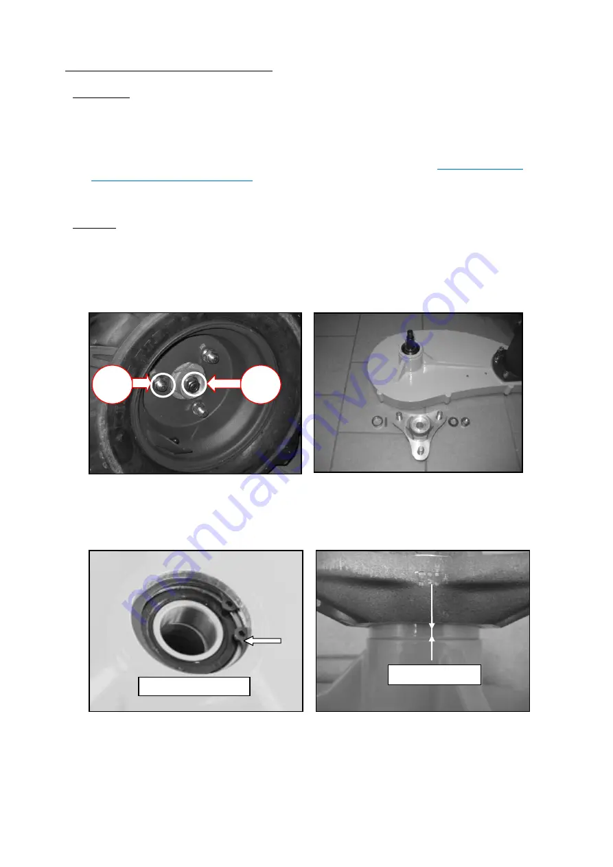
6.19 REPLACEMENT OF THE WHEEL SHAFT 

 
Dismounting: 

-


Remove the wheel (3 bolts holding the wheel) 

-


Undy the main wheel nut (Fig. 99) 

-


Remove the wheel hub (use wheel hub puller, if necessary heat up the hub for easier dismounting ), spacing 
ring and key 

-


Clean the wheel shaft (it must be able to slide through the bearings) 

-


Remove the wheel suspension housing cover, tensioning segment and the chain see 

6.18 Adjustment and 

replacement of the wheel driving chain


-


Pull the wheel shaft with  the chain sprocket out of the bearings 

-


If the bearings need to be replaced, remove the securing ring of the bearings and press the bearings out. 

 
Mounting: (take the above steps in reverse order) 

-


Lubricate the shaft with grease 

-


Degrease the taper seating of the wheel shaft and the wheel hub 

-


Install a new spacing ring, key, wheel hub and washer 

-


Ensure  a good seating of the wheel hub onto the taper of the wheel shaft 

-


Secure the main wheel nut with LOCTITE 243 and torque to 115 Nm (Fig. 99) 


              Fig. 99   


               Fig.100  


Fig. 101      


  Fig. 102 


Clearance 1-2 mm 

Securing the bearings 

1

-2

 m

m


115 
Nm 

60 
Nm 

Summary of Contents for ILD02 SG

Page 1: ...SM SG 2 Ev3 25062014 SERVICE MANUAL SPIDER ILD02 SG...

Page 2: ...t of the clutch 41 6 12 Sharpening and replacement of the blade 42 6 13 Replacement of the steering chain 43 6 14 Replacement of the steering motor 44 6 15 Replacement of the driving belts 45 6 16 Rep...

Page 3: ...13 Servomotor of the drive control 73 7 14 Control unit NBB 74 7 15 Starter starter relay 79 7 16 Clutch 79 7 17 Charging and ignition cables 80 7 18 Current measurement table ILD02 80 7 19 NBB elect...

Page 4: ...side of the mower marks the safe distance from the blades Transmission is by chains and gears on all four wheels The wheels are driven by two hydraulic motors through V belts Wheels are steered by an...

Page 5: ...5 84 SM SG 2 Ev3 25062014 1 SPECIAL SERVICE TOOLS Wooden block for lifted mower 400 x 200 x 200 2 pieces Straight lath for adjustment of wheel geometry length 1300 mm Engine oil filter release jig...

Page 6: ...6 84 SM SG 2 Ev3 25062014 Hydraulic oil filter release spanner Wheel hub puller Laser geometry adjustment tool P N PR006 P N PR002 P N PR001 P N PR001...

Page 7: ...7 84 SM SG 2 Ev3 25062014 Ampere meter CEM DT 9701 Voltmeter Ben electronic DT 830 D...

Page 8: ...Release replace belts Burned fuses Check fuses Faulty starter relay Replace relay Wrong fuel Use BA 95 only Erratic engine running Worn out spark plugs Replace spark plugs Fuel line is clogged Check...

Page 9: ...igh driving speed Lower the driving speed Mowed grass get stuck in the mowing mechanism Grass is too wet Wait till the grass dries Low engine speed Set the engine to maximum The mower goes but does no...

Page 10: ...M SG 2 Ev3 25062014 2 BASIC TECHNICAL SPECIFICATIONS Wheel RPM min Wheel RPM min wheels off the ground blades off SPIDER turtle rabbit engine RPM hydr oil temperature ILD02 56 min 110 min 3000 min 70...

Page 11: ...E SPIDER 4 1 DAILY a Check and add engine oil level Fig 1 b Check and clear engine and pump air intake screen Fig 2 Fig 3 c Check blades mounting sharpening and balancing Fig 4 Test of screw retighten...

Page 12: ...toothed segment and guide bushing of the cross Interflon FIN LUBE TF Fig 5 4 2 AFTER FIRST 8 HOURS a Change engine oil see 6 2 Replacement of the engine oil filter 4 3 AFTER 25 HOURS a Clean rough ai...

Page 13: ...0 HOURS a Clean paper air filter Fig 8 b Lubricate steering chain spray Interflon FIN LUBE TF Fig 9 c Tighten steering chain Fig 10 Fig 11 Slackness 20 mm paper air filter CHAIN SPRAY Interflon FIN LU...

Page 14: ...ange engine oil b Clean spark plugs c Clean dust and dirt from cylinder and cylinder head fins d Check tension of wheel driving chain see 6 18 Adjustment and replacement of the wheel driving chain 4 6...

Page 15: ...ic oil if applied see 6 3 Replacement of the hydraulic oil filter Paper air filter Valve Clearance when cold Inlet Exhaust 0 10 0 15 mm 0 004 0 006 in Adjustment Loosen the locknut A and adjusting bol...

Page 16: ...once per season Worn out spark plugs can caused signal interupts Tighten a new spark plugs 20 30 Nm b Change hydraulic oil and filter see 6 3 Replacement of the hydraulic oil filter c Change engine oi...

Page 17: ...17 84 SM SG 2 Ev3 25062014 5 ENGINE MAINTENANCE CHART ENGINE MAINTENANCE CHART KAWASAKI FS691V 24 HP Service more frequently under dusty conditions...

Page 18: ...e wheel transmission housing in the direction which you will be tilting the mower to Always tilt the mower control unit up in order to prevent the oil from leaking to the air filter and carburettor On...

Page 19: ...er put some oil on the filter sealing during assembly Fill up engine oil approximately 1 8 l 2 1 l when exchanging oil filter Fig 23 Fig 24 Check the oil level with the dipstick up to the upper dipsti...

Page 20: ...they can seal properly Fig 27 Fig 28 Fill up the hydraulic oil HV68 approximately 8 5 l Start the engine and move forward and backward to get rid of air in the hydraulic system the wheels must move s...

Page 21: ...31 Remove and tighten the screws back in the pump head Remove hydraulic tube A short nuts 2 and 3 simultaneously then 4 Fig 32 35 Remove hydraulic tube B long release nut 5 then simultaneously 6 and...

Page 22: ...Take the above steps in reverse order Install sufficient pump pulley tensioning disks to ensure a belt tension of 10 mm Loctite the screw on the pump shaft and the belt tensioning nuts LOCTITE 243 Sea...

Page 23: ...23 84 SM SG 2 Ev3 25062014 Fig 35 60Nm 70Nm...

Page 24: ...pump The braking effect will take place when the pressure in the hydraulic system drops engine shut down air in the hydraulic system after pushing the Emergency stop button When the pressure in hydrau...

Page 25: ...41 Release the tightening bolt of the hydromotor and both securing nuts M10 Fig 42 Dismount the driving belts XPB1450LW from the hydromotor pulley and hydromotor pulley Fig 43 Dismount the securing nu...

Page 26: ...et complete cross hydromotor and tight them by means of two nuts M10 don t tight Fig 42 Fig 45 Tight two springs TR1660 of the brake lever and fix them by means of the securing pin Fig 46 Mount new pu...

Page 27: ...elts XPB1450LW and secure the hydromotor by two nuts M10 Torque 45 Nm Fig 48 Mount the house 1SC06x0 7 to the throat XAL 12 1 14 1 5 of the brake cylinder Torque 45Nm Fig 49 Release the brake lever an...

Page 28: ...the brake cylinder and secure it with the securing nut on the fork rod Fig 53 Fig 52 Fig 53 Set the minimal revolution speed Release the breather screw and bleed the hydraulic system of the auxiliary...

Page 29: ...th springs from the rear bracket undo both bolts M10x45 and pull cylinder out from the fork rod and from the bracket remove spring bracket by driving out a key Mounting Install the spring bracket and...

Page 30: ...of the brake lining Dismounting Remove driving belts on the brake side see 6 15 Replacement of the driving belts Undo both lock nuts of the hydraulic motor Pull out brake strap Fig 2 Undo fork Fig 17...

Page 31: ...31 84 SM SG 2 Ev3 25062014 Mounting Take the above steps in reverse order Use a new split pins Fig 22 and 6...

Page 32: ...the pulley shaft LOCTITE 243 Fig 57 Mount the belts Fig 57 60 Tighten the belts by the tensioning screw Fig 55 58 Tighten the nuts of the hydraulic motor seating bolts Fig 58 Tighten the screws of the...

Page 33: ...33 84 SM SG 2 Ev3 25062014 Fig 59 Fig 60 Fig 61 Loctite the pulley bolt 50Nm...

Page 34: ...ig 65 Remove the drive belt B 1160 Fig 66 Fig 42 Fig 43 Fig 62 Fig 63 Fig 64 Mounting Install the clutch belt B 1160 Install sufficient pump pulley tensioning disks to ensure a belt tension of 10 mm a...

Page 35: ...35 84 SM SG 2 Ev3 25062014 Fig 65 Fig 66 Driving belt B 1160 Driving bearing box pulley Self securing nuts Driving belt B 1160 10 mm...

Page 36: ...e order Install the blade driving belt SPB 2410 Fig 67 Tension the belt SPB 2410 by means of the tensioning bearing box and belt ttensioner Fig 68 Loctite the bolts of the tensioning bearing box LOCTI...

Page 37: ...r cartridge and clutch cover Fig 62 63 Remove the belt B 1160 see 6 7 Replacement of the clutch driving belt B 1160 Remove belt tensioning nuts and the pulley front disk ATTENTION There is a locking g...

Page 38: ...0 3 0 6 mm it is necessary to adjust the clearance between the clutch disc and the brake with the adjusting nuts Adjust all three adjusting nuts Consequently check the clearance on all three adjustmen...

Page 39: ...ivate the brake Deactivated clutch has to stop the mechanism within 0 5s within 5 seconds with the mounted blades When the clutch is activated the brake disc must not warm up Each side of the brake mu...

Page 40: ...inserting and turning it Loctite and fasten the bolts of the bearing box driven driving LOCTITE 243 Install blade driving belt SPB 2410 and tension it see 6 8 Replacement of the blade driving belt SP...

Page 41: ...he FASTON plug Fig 74 75 Undo the main clutch bolt Fig 76 Remove the clutch Fig 74 Fig 75 Fig 76 Fig 77 Mounting Push the clutch cables through the inlet bushing of the case Loctite and fasten the mai...

Page 42: ...de must be in one level Fig 78 The blade must not have any cracks Fig 78 Sharpening Along the blade Fig 79 Blade angle about 40 Do not exeed 12 mm total metal removed at end of the blade Sharpen evenl...

Page 43: ...Disconnect the chain and connect the free chain section the left one to the new chain with a connecting link roller chain 084 1 MOFA 1 2 x 3 16 Fig 82 Fig 83 Turn the driving wheels to replace the old...

Page 44: ...ving chain Disconnect the chain and remove it from the motor sprocket Undo the set bolt and the bolt M10 and replace the motor Fig 86 Note the correct sequence of the tensioning pulleys and their dist...

Page 45: ...Pull the corner bracket off the shaft after removing bolts 1 2 and 3 Fig 73 Remove belts from the pulleys Fig 71 Fig 90 Mounting Mount the belt on the hydraulic motor pulley Fig 89 and bracket pulley...

Page 46: ...ing PA 6 onto the new angle gear Fig 93 Screws of the angle gear cover have to be secured using LOCTITE 243 Ensure the wheels slide in the gear theeth in a straight direction or adjust the steering ge...

Page 47: ...the distance ring under the rollers Install the stabilizer ball joint Install the taper locks on the steering shaft and tighten smoothly see 6 23 Adjustment of the wheel geometry Slide on spring and t...

Page 48: ...ansmission shaft groove Install the sprocket and tighten it with a screw longer than 30 mm after tightening replace the screw with the original screw securing it with LOCTITE 243 ATTENTION Do not knoc...

Page 49: ...lacement of the wheel driving chain Pull the wheel shaft with the chain sprocket out of the bearings If the bearings need to be replaced remove the securing ring of the bearings and press the bearings...

Page 50: ...ree capscrews no 3 for the middle one use a new self securing nut Fig 103 104 Insert the wheel housing spring pins no 2 Fig 103 Install the wheel shaft with sprocket and wheel hub see 6 19 Replacement...

Page 51: ...n one line using the laser geometry adjustment tool Fig 107 108 Distance between the corner bracket adges should be 1043 mm see Fig s below Fasten the right side of the stabilizer Check the clearance...

Page 52: ...he wheels must be off the ground Undo both capscrews no 7 holding stabilizer eye bracket no 5 Remove retaining ring 30 no 4 and pull off the stabilizer bracket from the stabilizer nylon bushing no 6 R...

Page 53: ...possible collision between the grubscrew and the driving pulley Fig 111 Hold a straight lath along the wheel housings on the left side of the machine and to the wheel rims on the right side of the mac...

Page 54: ...r to the minimum height of cut Disconnect the battery Disconnect the electric connector of the servo Release self locking nut and remove the pinion 14M Remove three countersunk screws Fig 115 Remove t...

Page 55: ...choke button elevation module disconnect sensors driving belts and hydraulic motors see 6 6 Replacement of the hydraulic motor expansion tank valve EDH breather hose bolt sets girder bolts stabilizer...

Page 56: ...liding bar 1st tooth in the 1st groove Fig 119 Assemble the girder bolts bolt sets stabilizer stiffener lift levers valve EDH expansion tank controller bracket choke button elevation module hydraulic...

Page 57: ...onnect the battery Fasten the lever nut to 30 Nm Adjustment of the neutral position Lift and support the mower the wheels must be off the ground Release the self securing nuts of servomotor connecting...

Page 58: ...s Connect the earth wire under the relay fixing screw during aasembly Check When the relay switches on the voltage must be on both heavy current relay connectors If not check the relay control voltage...

Page 59: ...r solenoid STOP button horn elevation module charger clutch driving servomotor NBB steering motor starter relay and control panel Remove the fuse box cover Undo the fuse box Starter relay Charger Carb...

Page 60: ...Engine minimum revolutions 1450rpm Engine working maximum revolutions 2900 rpm are pre set in Kawasaki Co You can increase them by shortening of the spring Fig 124 if necessary Carburettor discharge s...

Page 61: ...16025 7017 VALVE THROTTLE 16030 7003 VALVE FLOAT 16031 7002 FLOAT 16041 7050 SHAFT CARBURETOR CHOKE 16041 7051 SHAFT CARBURETOR THROTTLE 16073 7013 INSULATOR 16186 7006 VALVE ASSY CHOKE 172BA06115 BOL...

Page 62: ...from the gas tank and carburetor A carbon canister is used to store the fuel vapors The fuel vapors adhere to the carbon canister until the engine is started and engine vacuum can be used to draw the...

Page 63: ...63 84 SM SG 2 Ev3 25062014 Aluminium fuel tank Roll over valve Carbon canister Engine purge port...

Page 64: ...64 84 SM SG 2 Ev3 25062014 6 32 HYDRAULIC DIAGRAM Hydraulic oil pressure nominal 100 bar maximal 160 bar Activation deactivation of auxiliary drive brake activation 0 bar deactivation 6 7 bar...

Page 65: ...5 5 47 5 67 80 5 M 8x1 10 17 5 23 32 5 39 M 10x1 25 20 5 35 47 66 79 5 M 12x1 5 35 5 61 81 114 137 M 14x1 5 56 96 128 180 216 M 16x1 5 87 149 199 281 338 6 34 LUBRICATORS Interflon Fin Lube TF Chain s...

Page 66: ...n switch Emergency STOP Horn Carburretor solenoid Starter starter relay connectors clutch charging and ignition Elevation servomotors Fuses box Control panel Hours meter Moving servomotor NBB Elevatio...

Page 67: ...Use like main switch of power supply Check If main switch is presed contacts 1 2 switch off and 3 4 switch on Main switch 7 3 HORN Characteristics supply voltage 12 V red Horn BLACK control unit start...

Page 68: ...e straight driving driving direction This position is detected by the skid steer proximity switch located above the rear left angular gearbox on the left arm from hydraulic tank The hydraulic flow to...

Page 69: ...by elevation and skid steering module with the help of two elevation limit sensors These fix highest and lowest height of cut movement Correctly adjusted sensors have to stop servomotors elevation im...

Page 70: ...ne accelerator Characteristic Power supply 6 V control f 50 Hz Engine rpm servomotor 7 8 CARBURETOR SOLENOID electromagnetic valve to shut off fuel supply Characteristic power supply 12 V current drai...

Page 71: ...strictly follow the electric current value for which the fuses are designed Do not replace damaged fuses with fuses with a higher or lower rating These could cause large damage or even fire to the mow...

Page 72: ...ines red when blade is engaged Hour meter Control panel 7 11 BATTERY Characteristic Gel battery FBTX 20L BS 12V 18Ah Charging Only charge on gel battery setting recommend DECA SM1236 Dangerous supply...

Page 73: ...eels on the ground max steering load 30 A Steering servomotor Current measuring 7 13 SERVOMOTOR OF THE DRIVE CONTROL Characteristic 12 V PAL Power supply power supply 12 V Control power power supply 1...

Page 74: ...c leds LED 1 green POWER ON If led fails to come on check the power suplly If the power lead is OK control unit is probably at fault LED 2 yellow HF PRESENT Steady light when transmitter is switched o...

Page 75: ...v3 25062014 75 83 Attention During electro welding on the machine disconnect the receiver from the current supply Otherwise there is a risk of damage to the receiver s electronic system LED 1 LED 2 LE...

Page 76: ...OFF or O depends on the cable version Switch on the power on the Spider Operating with Spider Parameter Program Select the tab Com Port settings and select the com port you are using on your computer...

Page 77: ...To set the tolerance of the set point of the hydraulic servomotor When it is 0 the motor will adjust to the exact angle range for the neutral is 0 so servo will oscillate This can be resolved with in...

Page 78: ...b Load Save parameter to read all data from the NBB receiver and save them in a file You can also load a parameter file and write that to the NBB receiver When you have completed all parameter setting...

Page 79: ...e switch on 12 V and main wire voltage 12 V Coil resistant 4 1 ohm Starter solenoid 7 16 CLUTCH Characteristic Switching voltage 12 V Coil Resistance 3 4 ohm Current switch on 4 2 A Current measuring...

Page 80: ...f Current measuring Charging and ignition cables 7 18 CURRENT MEASUREMENT TABLE ILD02 Measured Current Voltage and Resistance Components Current Voltage Resistance A V ohm Solenoid carb 0 3 0 4 12 40...

Page 81: ...81 83 SM SG 2 Ev3 25062014 7 19 NBB ELECTRIC DIAGRAM ILD02 SG...

Page 82: ...82 83 SM SG 2 Ev3 25062014 7 20 ELEVATION AND SKID STEERING MODULE NBB ILD02...

Page 83: ...e danger Immediate servicing is necessary GENERAL ISSUE Information about ecological hydraulic oil for Spider ILD01 a ILD02 VALID FOR Spider ILD01 Spider ILD02 IMPORTANCE Information for Spider servic...

Reviews: