Dutch Pinball
–
Technical Support TBL FAQ
rev 0.51
Page 62 MPF Operations faq rel 0.70
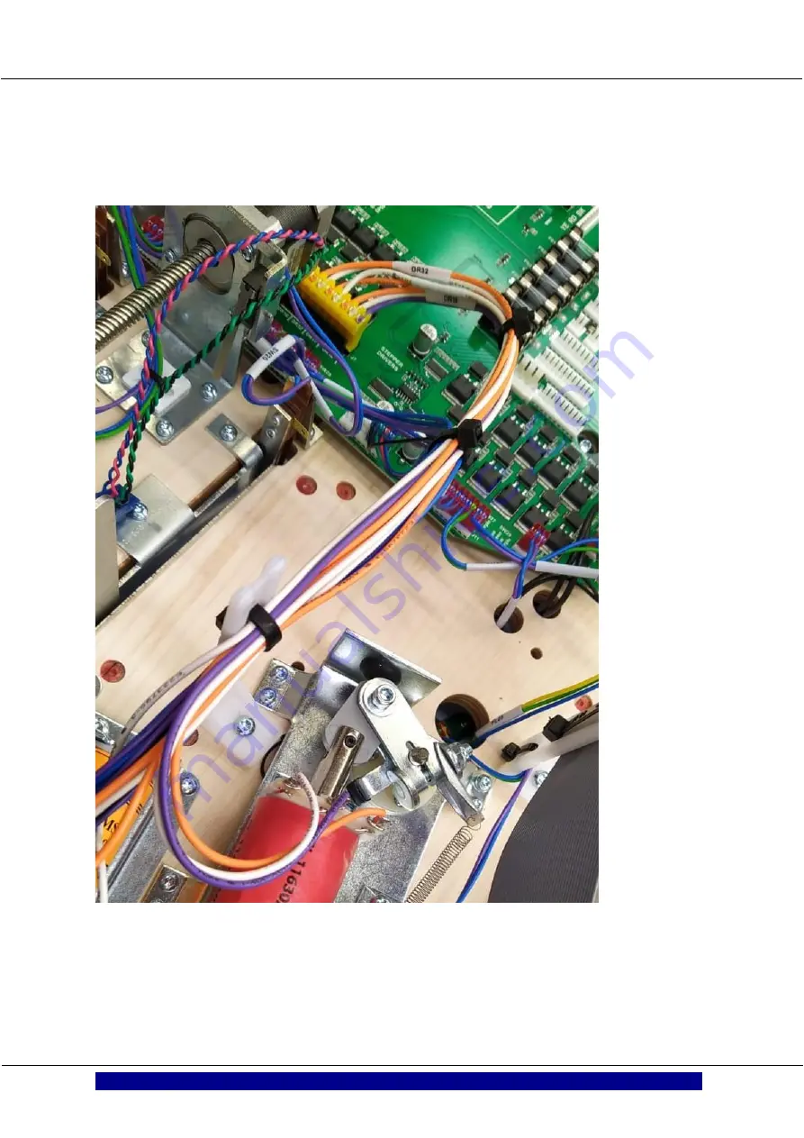
With a TBL which has the wiring correctly installed it looks like this picture. If it looks like this nothing has to be done.
Page 1: ...ch Pinball Technical Support TBL FAQ rev 0 51 Technical support TBL FAQ The Big Lebowski is a trademark and copyright of Universal Studios Licensed by Universal Studios Licensing LLC All Rights Reserv...
Page 2: ...or high voltage electronics please get professional support for this In general use your common sense Don t experiment Don t be a nihilist Only skilled and trained people are allowed to open this syst...
Page 3: ...of the launcher work 19 Do the opto and ball launcher switch work 20 Possible cause of zero pins dropping 21 Bowling pin coil check 22 Stuck releasepin 23 Ball is not getting up the ramp 23 Miscellan...
Page 4: ...the Rug Stepper motor 50 Mini PlayField MPF Operations FAQ rel 0 70 53 General overview 54 Working of the Cartoy 54 Switch overview 55 Cardoor stutters in open position 56 Cardoor stutters in closed p...
Page 5: ...full of the intentions of the builders They have taken pride and joy in building the TBL for you and hope it will give you joy for many years If you have questions or issues which are not solved in th...
Page 6: ...Dutch Pinball Technical Support TBL FAQ rev 0 51 Changelog compared to previous release Release 0 50 first release 23 may 2021 Release 0 51 added MPF kit installation guide...
Page 7: ...A 12390 Plungers are standard BW WPC type Left flipper Pinball Life Williams Bally Left Flipper Plunger and Crank Assembly right flipper Pinball Life Williams Bally Right Flipper Plunger and Crank As...
Page 8: ...Dutch Pinball Technical Support TBL FAQ rev 0 51 Page 8 Switch test faq rel 0 60 Switch test FAQ rel 0 60...
Page 9: ...pon opening the Menu Additional explanation is further in this manual How do you do this switch test First you need to open the coindoor and understand the controls you will see fitted in the coindoor...
Page 10: ...you see what the earnings are how many times a flipper was activated etc Player profiles With the TBL you can give players a profile If they select this profile when playing a game they can see their...
Page 11: ...tches or any unused switches during a certain number of games This number can be set by user in the Adjustment section If during booting an issue is seen it will be reported on the Attract screen If t...
Page 12: ...better roll a ball over it and see if this switch pops up on the display here Also a sound can be heard when a switch is activated and you can also see if there are no switches active when they should...
Page 13: ...Which switches are expected to be Active with NO game started Most likely it is And depending on the exact position of the Bowling launcher it can also be this If you see any other switches Active th...
Page 14: ...Dutch Pinball Technical Support TBL FAQ rev 0 51 Page 14 Switch test faq rel 0 60...
Page 15: ...Dutch Pinball Technical Support TBL FAQ rev 0 51 Page 15 Switch test faq rel 0 60...
Page 16: ...Dutch Pinball Technical Support TBL FAQ rev 0 51 Page 16 bowling operations faq rel 0 86 Bowling Operations FAQ rel 0 86...
Page 17: ...ore the first bowling pin when moving down and that triggers the software to activate the appropriate coils which pull the calculated bowling pins up So it has nothing to do with ball physically hitti...
Page 18: ...echanism is in place and the playfield can t drop in the cabinet Then set it vertical Let it carefully touch the top part of the backbox this to avoid damage You can put something in between like a cl...
Page 19: ...heck if its properly fixed pull by hand the ball launcher to see if it s securely fastened Use normal force when pulling The 2 5 mm Allen screw to tighten the launcher is found at the right and best a...
Page 20: ...be Ball at Top If you push Enter again the ball will be released and will roll down over the bowling playfield You should see OPTO appear briefly on the display Remember that for the coils to work in...
Page 21: ...If this happens check wiring of opto and if opto is properly aligned in front of the hole Also you will see on the right opto which is the Transmitter a shrinking sleeve is mounted The purpose of this...
Page 22: ...est Menu the switch which enables power supply to the 12 48 VDC circuits must be enabled If you select Bowling Alley you get the following choices If you select PINS you can select which pin you want...
Page 23: ...dy has passed it You can release the nuts holding the coilbracket and get some room to fiddle with it to get in in correct position Or you can bent it a little In Testmenu Solenoids you can find this...
Page 24: ...Dutch Pinball Technical Support TBL FAQ rev 0 51 Page 24 bowling operations faq rel 0 86 Miscellaneous checks The bowling alley has on one side a wiring hub Check if all connectors are properly seated...
Page 25: ...Dutch Pinball Technical Support TBL FAQ rev 0 51 Page 25 bowling operations faq rel 0 86 Switch Overview Bowling Alley...
Page 26: ...Dutch Pinball Technical Support TBL FAQ rev 0 51 Page 26 hang ups freeze P3 ROC lost issues faq rel 0 52 Freezes Hangups switches not responsive P3 ROC not found issues FAQ rel 0 52...
Page 27: ...osis Always try to gather the following info In case switches do not respond any more o Do the coindoor buttons still work If yes this should indicate there is USB communication PC P3 ROC o Do the fli...
Page 28: ...le cause is that there is a problem with the communication between the PC in the backbox and the P3 ROC under the main playfield First check to see if this can be the case is to check a Logfile which...
Page 29: ...present or the audio board cable On this USBkey a TBLupdate zipped should be present TBL checks for this file so it knows which USB to write to Export this file to the USBkey and open the file in you...
Page 30: ...y line 673 in get_events File home pinball dutchpinball source thebiglebowski dp main py line 837 in get_events IOError GetEvents ERROR Error in CollectReadData Attempt 1 to initiate the P ROC failed...
Page 31: ...en that connecting the Audioboard and P3 ROC board to the USB2 inputs is more reliable So as seen in below picture The grey cable is leading to the Audio board and the black cable is leading to the P3...
Page 32: ...es faq rel 0 52 Reseat USB connections to PC and P3 ROC Reseat the USB connectors to the P3 ROC under the main playfield and in the PC In case you are not familiar how to get under the playfield to th...
Page 33: ...m PC to P3 ROC This is a standard cable like 2 5 to 3 meter long from USB A to USB B A cable like used for connecting printers to a PC Very common available at any computer store Please do use a quali...
Page 34: ...Main Mother Board MMB below the main playfield Suppose the connectorpins of the P3 ROC don t have a 200 contact with the female header on the MMB it can be because of vibrations caused by playing the...
Page 35: ...field onto the front of the cabinet on the playfield support brackets Pull the playfield back with the playfield support brackets until the sliding mechanism clicks in the hinges ATTENTION Only contin...
Page 36: ...Dutch Pinball Technical Support TBL FAQ rev 0 51 Page 36 hang ups freeze P3 ROC lost issues faq rel 0 52 5V Power P3 ROC Fix Identify the P3 ROC board on the MMB...
Page 37: ...KE SURE TO TURN OFF THE GAME Prepare two wires preferably AWG 18 22 Red and Black and solder them EXACTLY as shown in the photo below If you do this carefully the 5V power to the P3 ROC is guaranteed...
Page 38: ...lly during transport these can shake loose but also vibrations caused by gameplay can loosen it Depending on the PC it can be equipped with 2x2Gb or 1x4Gb of RAM memory In this example the PC is equip...
Page 39: ...Dutch Pinball Technical Support TBL FAQ rev 0 51 Page 39 Rug toy faq rel 0 50 Rug Toy FAQ rel 0 50...
Page 40: ...l Technical Support TBL FAQ rev 0 51 Page 40 Rug toy faq rel 0 50 Principle of operation The rug toy is a fairly simple mechanism to understand In below picture you get an overview of the complete Rug...
Page 41: ...K switch Rug switch EOS back SW35 Dependable on the build date of your TBL the BACK switch can have 2 positions The one on the right picture is of the second built and you will find it on the right of...
Page 42: ...rel 0 50 Rugtoy makes noise when moving into third position This is usually caused by the fact that the subway is a little bent outward and the rug is running against which makes the steppermotor mak...
Page 43: ...position This is usually caused by the fact that the BACK switch is not detected or to late detected and the stepper motor keeps running pushing the Rug against the back wall Check if the BACK switch...
Page 44: ...inst the rugtoy The rug moves up and down and the range is dependable on the position of the FRONT and BACK switches The start position of the rug is that the rug is moved against the FRONT switch and...
Page 45: ...ssure can be checked by rotating the spindle manually However it is possible that rotating it manually generates enough electrical power to damage the control circuit So do this with the stepper motor...
Page 46: ...FAQ rev 0 51 Page 46 Rug toy faq rel 0 50 The spindle should run freely without having to use force The stepper motor is fixed with 4 screws If you loosen these 4 screws you can move the stepper moto...
Page 47: ...see fitted in the coindoor Coin Door buttons Normal function With the coin door buttons located at the inner side of the coin door to the left you can make all game adjustments you desire as well as c...
Page 48: ...ou see what the earnings are how many times a flipper was activated etc Player profiles With the TBL you can give players a profile If they select this profile when playing a game they can see their s...
Page 49: ...ll switches which are active at that moment If you have doubts about a certain switch you can check the correct working here Push the switch or even better roll a ball over it and see if this switch p...
Page 50: ...the MPF you will find a moving door behind which the car is placed This Car Door is moved by a stepper motor The rug on the playfield is also controlled by a stepper motor Remember that for the stepp...
Page 51: ...l get the following In this mode the door will move only once Pushing will open it pushing will close it However if you push Enter it will go to the looping mode In this mode the motor will run contin...
Page 52: ...Dutch Pinball Technical Support TBL FAQ rev 0 51 Page 52 Rug toy faq rel 0 50...
Page 53: ...Dutch Pinball Technical Support TBL FAQ rev 0 51 Page 53 MPF Operations faq rel 0 70 Mini PlayField MPF Operations FAQ rel 0 70...
Page 54: ...ar has in fact 3 switches One switch is the Car Closed switch SW 54 you could see this as a Home switch and the other 2 are the 2 parking targets SW52 and SW53 They have both the same functionality an...
Page 55: ...Page 55 MPF Operations faq rel 0 70 Switch overview The ramp had two switches Mini Ramp enter SW51 and Mini Ramp made SW56 you see them both in below pictures When shooting the plastic ramp it will c...
Page 56: ...properly Only one has to be closed in order for TBL to detect cardoor is open The switches will need adjustment to make sure they trigger when the cardoor is in open position To get access to the lea...
Page 57: ...tion Solution is 1 to re adjust the switch and if that doesn t help 2 replace the switch It s a standard DB5 switch like can be seen at https www pinballlife com williamsbally sub microswitch 5647 126...
Page 58: ...venient for reference purposes with your MPF These pictures don t show the backboard installed The MPF is connected with 1 screw to the backboard and 3 screws to the main playfield Clearly shown in th...
Page 59: ...e you have bashed the Car the upper flipper will stop working till next time the ball enters the MPF So this is not an error but a feature Ball comes down Walter ramp after Jesus ramp was shot If you...
Page 60: ...a weak flipper You can fix this via installing a new connector but typically desoldering and resoldering a wire on the coil is easier as mounting a new connector error was made on the connector So in...
Page 61: ...ddle of the coil Again DO NOT look at the color of the wire as this can be different with you purely to the position of the wire on the connector versus the position of the wire on the coil This makes...
Page 62: ...h Pinball Technical Support TBL FAQ rev 0 51 Page 62 MPF Operations faq rel 0 70 With a TBL which has the wiring correctly installed it looks like this picture If it looks like this nothing has to be...
Page 63: ...will display all switches which are active at that moment If you have doubts about a certain switch you can check the correct working here Push the switches on the MPF parking targets loop ramp ramp m...
Page 64: ...e ball launcher left and right On the MPF you will find a moving door behind which the Car is placed This Car Door is moved by a stepper motor The rug on the playfield is also controlled by a stepper...
Page 65: ...rel 0 70 Select the stepper motor you want to test In this case we take the Car Stepper If you select it you will get the following In this mode the door will move only once Pushing will open it push...
Page 66: ...termittent problem this can be useful to diagnose it or to adjust a switch Cardoor should go open and close smoothly If the Cardoor stutters against the parking targets you will need to adjust the par...
Page 67: ...Dutch Pinball Technical Support TBL FAQ rev 0 51 Page 67 MPF removal and installation guide rel 0 53 Mini PlayField MPF Removal and installation guide rel 0 53...
Page 68: ...e steppermotor was re positioned under the MPF Called Built type B in the manual The difference is that with the old boardset the connector for the opto s of the scoop is under the playfield where wit...
Page 69: ...it carefully touch the top part of the backbox this to avoid damage You can put something in between like a cloth to reduce the chance of damage even further To make sure it doesn t drop on your head...
Page 70: ...rev 0 51 Page 70 MPF removal and installation guide rel 0 53 Step 3 Only valid for built type B disconnecting the Opto connector Disconnect the connector going to the opto s of the MPF After this is...
Page 71: ...ove the roof by loosen the two Allen screws Disconnect the cable going to the roof Remove the 4 screws holding the Right ramp at the entrance and end and put ramp aside It can remain in the flipper Lo...
Page 72: ...TBL FAQ rev 0 51 Page 72 MPF removal and installation guide rel 0 53 Carefully lift the MPF and disconnect the ribbon flatcable going to the PCB and the cable going to the stepper motor Remove the MP...
Page 73: ...stalled If you have the built type B with an opto cable guide this cable coming from the opto s of the scoop through the same hole as the flatcable If you have type A you can skip this step Make sure...
Page 74: ...ith loose opto cable raise the playfield vertically and connect the optocable Set the playfield horizontal again Connect the roof to the roof powercable Step 6 Test functionality Now time to test if a...
Page 75: ...and see if this switch pops up on the display here Also a sound can be heard when a switch is activated and you can also see if there are no switches active when they should not be LED tests If you s...
Page 76: ...On the MPF you will find a moving door behind which the car is placed This Car Door is moved by a stepper motor The rug on the playfield is also controlled by a stepper motor Remember that for the ste...
Page 77: ...it stutters when closed you will have to adjust the switch there Step 7 Wrap up If everything is tested OK you can turn your TBL off Place all screws in place which secure the MPF don t forget the one...
Page 78: ...Dutch Pinball Technical Support TBL FAQ rev 0 51 Page 78 Operate TBL from keyboard rel 0 50 Operate TBL from keyboard rel 0 50...
Page 79: ...or menu buttons ESC Volume Down Volume Up ENTER 7 8 9 0 If you push ESC you go into Linux So to go into the Testmenu just press 0 7 8 9 0 function as menu control buttons just as in the coindoor So yo...
Page 80: ...Dutch Pinball Technical Support TBL FAQ rev 0 51 Page 80 Restore power setting Bios faq rel 0 50 Restore Power Setting BIOS FAQ rel 0 50...
Page 81: ...this occurs the game will not turn on when you engage the main power switch of the game Follow these steps to enable the Power On setting in the BIOS of the PC 1 Make sure the game is turned off with...
Page 82: ...position The PC game will not boot 4 To turn on the PC game you have to jump two pins on the CPU Board The two pins that need to be connected are in the bottom left of the CPU board 5 Carefully connec...
Page 83: ...Restore power setting Bios faq rel 0 50 6 Because you removed the SATA cable the PC will now boot directly to BIOS 7 Connect a Keyboard to the PC and press use the arrow keys to go to the advanced se...
Page 84: ...os faq rel 0 50 9 Press Enter to enter the Chipset Configuration 10 Press the down arrow key until you see this option because the screen is cut off on the bottom you can t see the highlighted option...
Page 85: ...e Changes and Exit and press Enter 14 Select Yes and press Enter 15 The game now reboots and will show the start page of the BIOS screen again 16 Turn off the game with the Main Power Switch 17 Reconn...
Page 86: ...Dutch Pinball Technical Support TBL FAQ rev 0 51 Page 86 Restore SSD faq rel 0 85 Restore SSD FAQ rel 0 85...
Page 87: ...the image from the link provided by DP Connect the SSD to which the image has to be written to your PC For this you can use commercially available SATA to USB cables The SSD itself is a standard comm...
Page 88: ...Dutch Pinball Technical Support TBL FAQ rev 0 51 Page 88 Restore SSD faq rel 0 85 Start Macrium Select Restore Browse for an image or backup file to restore...
Page 89: ...Pinball Technical Support TBL FAQ rev 0 51 Page 89 Restore SSD faq rel 0 85 Now select the Image you have downloaded and want to restore If you click Open you will see below picture Click on Restore...
Page 90: ...Support TBL FAQ rev 0 51 Page 90 Restore SSD faq rel 0 85 Select Destination Target disk Make sure you select the correct drive and don t write it to your PC drive Click Next You will now get a Resto...
Page 91: ...Dutch Pinball Technical Support TBL FAQ rev 0 51 Page 91 Restore SSD faq rel 0 85 Tick the box and click Continue Process will start...
Page 92: ...Dutch Pinball Technical Support TBL FAQ rev 0 51 Page 92 Restore SSD faq rel 0 85 After finishing the Restore it will be reported and you are finished Now you can mount the SSD in the TBL...
Page 93: ...empty spot If none available you can remove wifi dongle if present or the audio board cable On this USBkey a TBLupdate zipped should be present TBL checks for this file so it knows which USB to write...
Page 94: ...mage Put USB key in an empty spot If none available you can remove wifi dongle if present or the audio board cable On this USBkey the database file you want to use should be present Connect mouse and...
Page 95: ...Dutch Pinball Technical Support TBL FAQ rev 0 51 Page 95 Restore SSD faq rel 0 85 Go to TBL Go to the latest release in this case 0 55...
Page 96: ...into this folder Now you can delete the old backup file or just rename it for instance to old_database right click on the file The selected file in below screen is the earlier backed up file through...
Page 97: ...v 0 51 Page 97 Restore SSD faq rel 0 85 Rename the earlier back upped file to database db and you are done You can now turn TBL OFF ON and see the old settings restored on the new SSD So audits are ba...
Page 98: ...al file you will find direct in the main TBL folder You can copy it from your old SSD to your new SSD If you want to be connected to internet just go with the mouse to top right corner of display and...
Page 99: ...Dutch Pinball Technical Support TBL FAQ rev 0 51 Page 99 System program error popup rel 0 80 System program Error pop up FAQ rel 0 80...
Page 100: ...l 0 80 Sometimes it happens that Linux Ubuntu shows a pop up with an error message How to fix this This is also described in a Pinside post seen at A lotta ins a lotta outs TBL maintenance thread Dutc...
Page 101: ...the top Chose for Xterm and a terminal is opened Or chose for Terminal but than you you should push ALT TAB to get it displayed Type sudo rm var crash and push Enter Now a password will be asked This...
Page 102: ...Dutch Pinball Technical Support TBL FAQ rev 0 51 Page 102 Where to hook up my mods faq rel 0 81 Where to hook up my Mods FAQ rel 0 81...
Page 103: ...DC power is at the moment of writing this application note the Coolermaster model G550M You can see more info on this PSU at https www techpowerup com review cooler master g550m The Coolermaster Power...
Page 104: ...ecting Mods to your TBL is always at your own risk the best easiest way to get the required electrical power is the spare connector in the backbox next to were the Translite is connected The used conn...
Page 105: ...sed connector here is the Mini Fit Jr 1x5p Rec 39 01 4050 Housing 39014050 Molex Connector Housing Pull Tabs UL 94V 2 Farnell Netherlands Contacts 1586315 1 Amp Te Connectivity Contact VAL U LOK Serie...
Page 106: ...e to much power 4 if you take by chance one of the led driving channels those can only deliver 20mA and overloading it can blow a channel s on the PDled bord 5 TBL owners with a lit up Apron will see...
Page 107: ...Dutch Pinball Technical Support TBL FAQ rev 0 51 Page 107 Audio faq rel 0 51 Audio FAQ rel 0 51...
Page 108: ...or when you hear the sound If it than stops it s the stepper motor s When you open the coindoor the voltage towards the stepper motors is switched off sound caused by stepper motor s disappears I hear...
Page 109: ...9 Audio faq rel 0 51 Check if the polarity of all the speakers is connected properly Speaker panel left speaker right speaker The speaker wires run to the audioboard bottom left Red is and Black is Th...
Page 110: ...er you will see at one of the connections a red dot this is where the is and red wire goes Cabinet speaker is connected via 2 pairs of cables running to the audio board and connected to the right bott...
Page 111: ...Dutch Pinball Technical Support TBL FAQ rev 0 51 Page 111 Audio faq rel 0 51 Check dipswitch settings The Audio board has a dipswitch Default settings are shown in below pictures...
Page 112: ...Dutch Pinball Technical Support TBL FAQ rev 0 51 Page 112 Revised ball gate installation kit rel 0 92 Revised ballgate kit Installation Guide only the part below the playfield...
Page 113: ...ed are some soldering skills shrinking sleeve Torx drivers Installation Step 1 Remove the springs from the ball gate s Carefully remove the lockdown bar and playfield glass Remove all five balls from...
Page 114: ...you will have an easier access to the ball gates You find tone in the top left corner and one to the right just below the upper playfield Use a long nose pliers or a long pin with a curved end to de...
Page 115: ...s means the locking mechanism is in place and the playfield cant drop in the cabinet Than set it vertical Let it carefully touch the top part of the backbox this to avoid damage You can put something...
Page 116: ...isting ball gates Identify the ball gates s you want to replace with the new type You will find them at the bottom of the playfield De solder the existing wires orange and white from the coil tabs Rem...
Page 117: ...ix the ball gate with the 2 screws from the old ball gate Note with the left ball gate make sure the wires exit from the right so they stay away as much as possible from the metal on the side of the p...
Page 118: ...o the coil wires Slide some shrinking sleeve over one end of the original orange and white wire solder them individually to the red wires it doesn t matter which red wire you solder it to of the new b...
Page 119: ...ble for testing Important notice the stepper motors are operated at 12VDC and coils are operated at 48VDC With an open coin door these voltages are disabled so the coils and stepper motors will NOT wo...
Page 120: ...Dutch Pinball Technical Support TBL FAQ rev 0 51 Page 120 EA apron installation guide rel 1 0 Early Achiever Apron Installation Guide Rev 1 0...
Page 121: ...older 3x M3 x 6 bolt 3x M3 Washer 2x 4 2 x 13 Screw Torx 20 Installation Step 1 Remove old Apron Carefully remove the lockdown bar and playfield glass Remove all five balls from the Ball Trough Lift t...
Page 122: ...n installation guide rel 1 0 Step 3 Remove old and install new Ball Hole Guide Replace the old Ball Hole Guide with the new included EA Ball Hole Guide Step 4 Mount Circuit Board Before installing the...
Page 123: ...tion guide rel 1 0 Mount the Circuit Board with the included M3 bolts and washers Step 5 Install Ribbon Cable Put the playfield in the upright position and make sure the playfield can t fall down Loca...
Page 124: ...0 51 Page 124 EA apron installation guide rel 1 0 Remove the bottom left bolt of the P3 ROC mount and use the same bolt to mount the cable tie holder Insert one end of the ribbon cable in the Mod Hea...
Page 125: ...Dutch Pinball Technical Support TBL FAQ rev 0 51 Page 125 EA apron installation guide rel 1 0 Install the two Cable Mounts like this...
Page 126: ...Dutch Pinball Technical Support TBL FAQ rev 0 51 Page 126 EA apron installation guide rel 1 0 Plug the other end of the ribbon cable in the circuit board...
Page 127: ...Dutch Pinball Technical Support TBL FAQ rev 0 51 Page 127 EA apron installation guide rel 1 0 Use the cable ties to secure the ribbon cable...
Page 128: ...8 EA apron installation guide rel 1 0 Step 6 Install Apron Lower the playfield and rest the playfield onto the front of the cabinet on the playfield support brackets Place the new Apron and make sure...
Page 129: ...board You can now lower the playfield back into the game Step 8 Software Update To see the light show on the Apron you need to update the software to at least version 0 52 Download the update from the...
Page 130: ...Dutch Pinball Technical Support TBL FAQ rev 0 51 Page 130 MPF kit installation guide rel 1 0 Mini PlayField MPF kit Installation Guide rel 1 0...
Page 131: ...so for spare 2x M4 screw for cardoor 1 for spare 1 x plastic holder for repositioning rug EOS switch 1x new flipperbushing spare 1x isolation ring 1x protection sheet for playfield Installation Step 1...
Page 132: ...ed to secure it with a strap Also we recommend to put something over the bowling alley to avoid screws falling into it Once the stepper motor is removed the cardoor can freely move and might scratch y...
Page 133: ...4 screws holding the stepper motor assy to the playfield Remove the assy and put it aside No longer needed Loosen the 2nd part of the coupling nut and take out the middle part Now a last part is on t...
Page 134: ...rel 1 0 Step 2 Remove upper flipper from under the main playfield Next step is to remove the upper flipper This is connected to the coil below the playfield Loosen the screw holding the axis of this f...
Page 135: ...elocate the EOS switch of the rugtoy If you don t to this the rugtoy will hit at the end the stepper motor under the MPF Locate the EOS switch as seen in below picture Place the delivered switchholder...
Page 136: ...the roof by loosen the two Allen screws Disconnect the cable going to the roof Remove the 4 screws holding the Right ramp at the entrance and end and put ramp aside It can remain in the flipper Loosen...
Page 137: ...your worktable Step 5 Removing the door with car Remove the wall which is fixed with 4 screws Remove the loopramp which is held with 4 screws and unplug the connector from the PCB at the bottom Remov...
Page 138: ...ew the old ones by unscrewing the 4 screws and remount the new one with 2 screws 3 5x13 The targets connect to 46 and 47 All cabling is labeled and on the PCB you will see the corresponding numbering...
Page 139: ...hnical Support TBL FAQ rev 0 51 Page 139 MPF kit installation guide rel 1 0 Mount the stepper motor with the axis through the bushing with connectorplug facing backwards as shown on the picture Use 4...
Page 140: ...2 screws is recommended Put the door on the axis Please do note the axis has a flat part which should align with the flat part in the door hole If you look closely you will see this Slide the door ove...
Page 141: ...hing Place the walls back Guide the roof light cable between the loopramp and MPF Make sure the cabling is flush against the underside of the MPF If its not flush with the MPF it can block the Jesus l...
Page 142: ...coming from the opto s of the scoop through the same hole as the flatcable Plug now the plug of the stepper motor cable in place in the stepper motor and do the same with the flatcable in the PCB Put...
Page 143: ...an carry out any test you desire to check if something is working properly Switch test If you activate this test it will display all switches which are active at that moment If you have doubts about a...
Page 144: ...s the ball launcher left and right On the MPF you will find a moving door behind which the car is placed This Car Door is moved by a stepper motor The rug on the playfield is also controlled by a step...
Page 145: ...guide rel 1 0 Select the stepper motor you want to test In this case we take the Car Stepper If you select it you will get the following In this mode the door will move only once Pushing will open it...
Page 146: ...tested OK you can turn your TBL off Place all screws in place which secure the MPF don t forget the one coming from the backboard on the backsite Reinstall the roof Reinstall the wireform and right r...