


Working basis
16
Service manual 567 classic - 01.0 - 10/2015
3.4
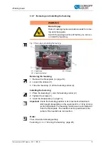
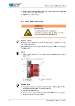
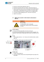
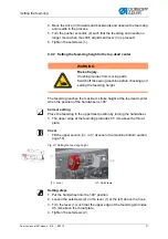
Flats on shafts
Screw the screw
on to the flat
Fig. 8: Flats on shafts
Some shafts have flat surfaces at those points where the components are
screwed on. This stabilizes the connection and makes adjustment easier.
Always ensure that the screws lie completely on the surface.
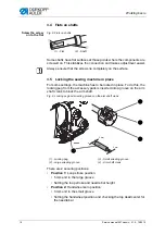
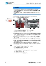
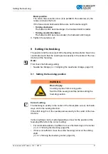
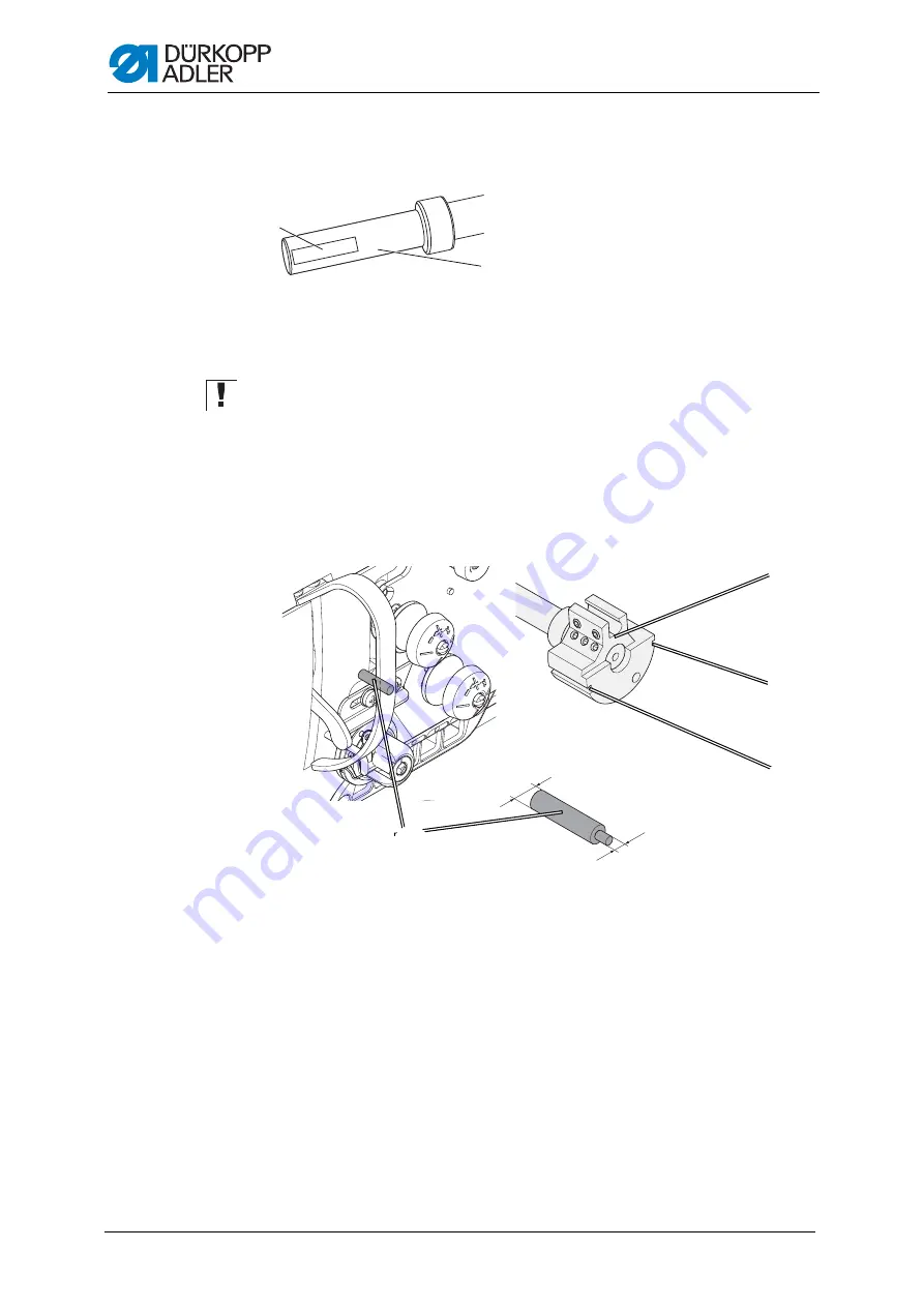
3.5
Locking the sewing machine in place
For some settings, the machine has to be locked in place. To do this, the
locking peg from the accessory pack is inserted into a groove on the arm
shaft crank to block the arm shaft.
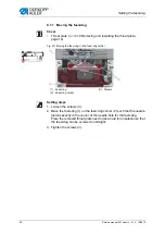
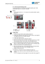
Fig. 9: Locking peg and arresting grooves on the arm shaft crank
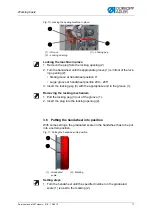
There are 2 securing positions:
•
Position 1:
Loop stroke position
• 5 mm end in the large groove
• Setting the loop stroke and needle bar height
•
Position 2:
Handwheel zero position
• 3 mm end in the small groove
• Setting the handwheel position and checking the top dead center for
the needle bar
2
1
(1) - Flat
(2) - Shaft
5 mm
3 mm
(1) - Locking peg
(2) - Large arresting groove
(3) - Small arresting groove
(4) - Arm shaft crank
③
①
④
②
Summary of Contents for 567 CLASSIC
Page 1: ...567 classic Service manual...
Page 20: ...Working basis 18 Service manual 567 classic 01 0 10 2015...
Page 79: ......


