background image

Machine head 

41

Service Instructions 911-211 - 02.0 - 10/2016

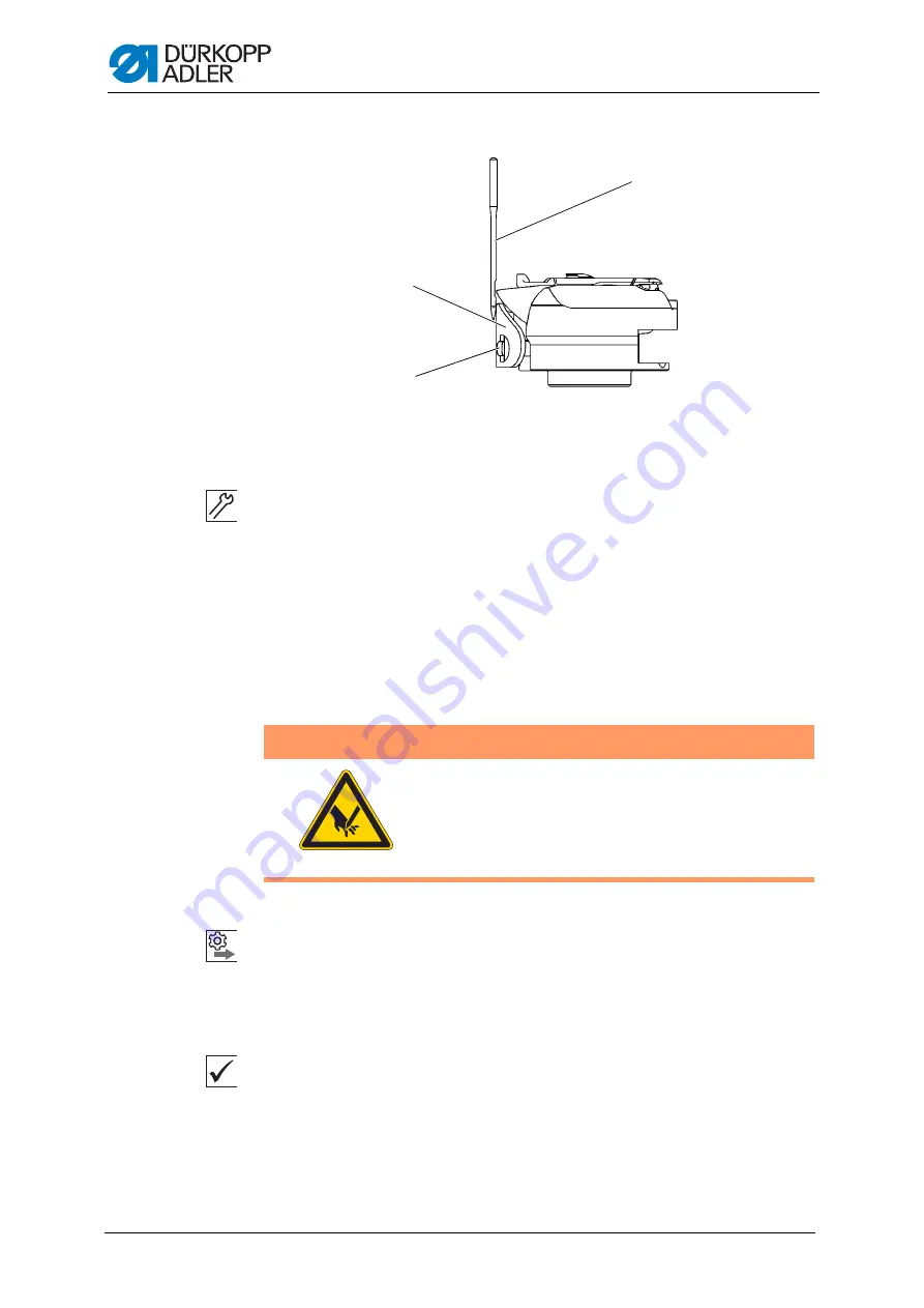
Fig. 28: Setting the needle guard

To set the needle guard:

1.

Press and turn the hand crank and check how far the needle guard (1) 
pushes the needle (3) away.

2.

Turn the screw (2) such that the needle guard (1) just pushes the 
needle (3) far away enough so that it is not touched by the hook tip:

• for pushing away more: Turn counterclockwise

• for pushing away less: Turn clockwise

4.4.5 Setting the needle guide 

Order

First, check the following setting:

• A straight and undamaged needle has to be inserted (

 Operating 

Instructions

)

Proper setting

1.

Machine locked in place at position 1 (


p. 28

).

The needle guard pushes the needle just enough away so that it can-
not be touched by the hook tip.

(1)

- Needle guard

(2)

- Screw

(3)

- Needle

WARNING

Risk of injury from sharp and moving parts!

Puncture or crushing possible.

Switch off the machine before you check and set 
the needle guide.

Summary of Contents for 911-211

Page 1: ...Service Instructions 911 211...

Page 2: ...er AG and protected by copyright Any reuse of these contents including extracts is prohibited without the prior written approval of D rkopp Adler AG Copyright D rkopp Adler AG 2016 IMPORTANT READ CARE...

Page 3: ...onal 23 3 4 Flats on shafts 23 3 5 Aligning the machine head 24 3 6 Locking the machine in place 28 3 7 Putting the machine into position 29 4 Machine head 30 4 1 Positioning the arm shaft crank 30 4...

Page 4: ...Checking the machine zero point 83 5 2 Changing the drives 84 5 2 1 Changing the sewing motor 84 5 2 2 Changing the X drive 86 5 2 3 Changing the Y drive 87 5 3 Checking the play between toothed rack...

Page 5: ...Cleaning the machine 147 8 1 2 Cleaning the motor fan mesh 148 8 2 Lubricating 149 8 2 1 Lubricating the machine head 150 8 2 2 Lubricating the hook 151 8 3 Servicing the pneumatic system 152 8 3 1 Se...

Page 6: ...Table of Contents 5 Service Instructions 911 211 02 0 10 2016...

Page 7: ...structions intended These instructions are intended for Specialists This group has the appropriate technical training for performing maintenance or repairing malfunctions With regard to minimum qualif...

Page 8: ...y control panel Important Special attention must be paid to this point when performing a step Information Additional information e g on alternative operating options Order Specifies the work to be per...

Page 9: ...dards and regulations D rkopp Adler cannot be held liable for any damage resulting from Breakage and damage during transport Failure to observe these instructions Improper use Unauthorized modificatio...

Page 10: ...About these instructions 9 Service Instructions 911 211 02 0 10 2016...

Page 11: ...rts could impair safety and damage the machine Only use original parts from the manufacturer Transport Use a lifting carriage or forklift to transport the machine Raise the ma chine max 20 mm and secu...

Page 12: ...ed in warnings Warnings in the text are distinguished by color bars The color scheme is based on the severity of the danger Signal words indicate the severity of the danger Signal words Signal words a...

Page 13: ...n fatal injury if ignored This is what a warning looks like for a hazard that could result in moderate or minor injury if the warning is ignored Puncture Crushing Environmental damage Symbol Type of d...

Page 14: ...nvi ronmental damage if ignored This is what a warning looks like for a hazard that could result in property damage if ignored CAUTION Type and source of danger Consequences of non compliance Measures...

Page 15: ...cess cabling neatly in proper cable snakes 2 Bind together the cable loops with cable ties Tie loops wherever possible to fixed parts Important The cables must be secured firmly 3 Cut off any overlapp...

Page 16: ...icular time 3 3 1 Access to the underside of the machine Cover To access the components on the underside of the machine swivel up the machine head Fig 1 Access to the underside of the machine Swivelin...

Page 17: ...3 Swivel down the machine head 4 Latch the locking lever 1 under the tabletop 3 3 2 Removing and assembling the motor cover Fig 2 Removing and assembling the motor cover Removing the motor cover To r...

Page 18: ...oosen screws 2 and countersunk screw 3 3 Remove the arm cover 4 Placing the arm cover To place the arm cover 1 Place the arm cover 4 2 Tighten the countersunk screw 3 3 Tighten the screws 2 4 Press do...

Page 19: ...placing the head cover Fig 4 Removing and placing the head cover Removing the head cover To remove the head cover 1 Loosen the screws 1 2 Remove the head cover 2 Placing the head cover To place the he...

Page 20: ...cing the rear cover Fig 5 Removing and placing the rear cover Removing the rear cover To remove the rear cover 1 Loosen all 3 screws 1 2 Take off the rear cover 2 by moving it back Placing the rear co...

Page 21: ...Removing and placing the toothed belt cover Removing the toothed belt cover To remove the toothed belt cover 1 Loosen all 4 screws 1 2 Remove toothed belt cover 2 Placing the toothed belt cover To pl...

Page 22: ...n flap Opening the bobbin flap To open the bobbin flap 1 Switch on the machine and reference it 2 Remove the sewing material holder 3 Press the Threading mode button The bobbin flap 1 pivots to the si...

Page 23: ...e Fig 8 Removing and placing the sliding plate Removing the sliding plate To remove the sliding plate 1 Reach through the hole 2 from below and lift the sliding plate 1 2 Remove the sliding plate 1 Pl...

Page 24: ...the burner cover 1 Loosen both screws 2 2 Remove the burner cover 1 Placing the burner cover To place the burner cover 1 Place the burner cover 2 2 Tighten both screws 1 3 4 Flats on shafts Fig 10 Fl...

Page 25: ...level with the cutout in the table top 2 Height X of the transport system is identical on the left and the right both at the rear and the front position of the carriage Check the height using the flat...

Page 26: ...up the machine head p 15 4 Set the height 5 Check the position of the machine head again Front Carriage at rear position Carriage at front position Fig 13 Aligning machine head 3 carriage at rear pos...

Page 27: ...turn clockwise 4 To adjust the locking mechanism loosen the screws 6 5 Move the clamp 7 up or down To slacken the locking mechanism Slide the clamp up To tighten the locking mechanism Slide the clamp...

Page 28: ...ns on the left not shown and on the right 9 to adjust the height of the machine head at the rear higher turn clockwise lower turn counterclockwise 9 Test the height of the base plate using flat materi...

Page 29: ...securing positions Position 1 Loop stroke position 5 mm end in the large slot Setting the loop stroke and needle bar height Position 2 Needle at top dead center 3 mm end in the small slot Checking th...

Page 30: ...g the machine into position For some settings the machine must be put into a certain position using the hand crank on the arm cover The machine has no handwheel Fig 19 Putting the machine into positio...

Page 31: ...rm shaft crank 1 Loosen all threaded pins 2 on the arm shaft crank 1 2 Turn the arm shaft crank 1 such that the threaded pins 2 are seated completely on the flat of the arm shaft 3 Push the arm shaft...

Page 32: ...after making a change on either of the toothed belt wheels 4 2 1 Setting the upper toothed belt wheel Proper setting The 2 threaded pins for the upper toothed belt wheel are seated flush on the flat C...

Page 33: ...r to push the toothed belt 4 back again 4 2 2 Setting the lower toothed belt wheel Proper setting Both threaded pins for the lower toothed belt wheel are seated flush on the flat of the lower shaft Th...

Page 34: ...out being pushed away 4 Screw both threaded pins 4 firmly in place 4 3 Aligning the needle bar linkage Order First check the following setting A straight and undamaged needle has to be inserted Operat...

Page 35: ...ok and needle 4 4 1 Setting the loop stroke position Information The loop stroke is the path length from the bottom dead center of the nee dle bar up to the height where the hook tip picks up the loop...

Page 36: ...s Cover Swivel up the machine head p 15 Fig 25 Setting the loop stroke position 2 To set the loop stroke position 1 Lock the machine in place at position 1 p 28 2 Loosen all 4 threaded pins 5 for the...

Page 37: ...e is locked in place at position 1 p 28 The hook tip is level with the lower third of the groove on the needle Disturbances caused by an incorrect needle bar height Damage to the hook tip Jamming of t...

Page 38: ...e height of the needle bar 2 so that the hook tip 4 is in the middle of the lower third of the groove on the needle 5 Important When doing this take care not to twist the needle The groove 5 must face...

Page 39: ...mum 0 1 mm distance between the hook tip and the groove for the needle Cover Swivel up the machine head p 15 WARNING Risk of injury from moving parts Crushing possible Switch off the machine before yo...

Page 40: ...1 4 Move the hook support 3 sideways such that the distance between the hook tip 5 and the groove for the needle 4 is 0 1 mm at most without the hook tip 5 touching the needle 5 Tighten the screws 2...

Page 41: ...ne locked in place at position 1 p 28 The needle guard pushes the needle away just enough so that it is not touched by the hook tip WARNING Risk of injury from sharp and moving parts Puncture or crush...

Page 42: ...away more Turn counterclockwise for pushing away less Turn clockwise 4 4 5 Setting the needle guide Order First check the following setting A straight and undamaged needle has to be inserted Operatin...

Page 43: ...s Fig 29 Setting the needle guide To set the needle guide 1 Loosen the screws 1 2 Remove the throat plate 2 3 Rotate the machine to position 1 p 28 4 Loosen the screw 4 5 Move the needle guide 3 as cl...

Page 44: ...gap appears for the thread If the hook tip is located below the bobbin case lifter the bobbin case lifter must open so that the thread can also slide past in that position So that the thread can slip...

Page 45: ...el up the machine head p 15 Fig 31 Setting the lifting gap standard hook bearing To set the lifting gap 1 Loosen the screw 2 2 Push the cover 3 downwards 3 Loosen the threaded pin 1 4 Set the bobbin c...

Page 46: ...oint 1 there must be still be a gap between the nose of the bobbin case and the middle sec tion holder Information The lifting gap on the special hook bearing used for belts is markedly wider than the...

Page 47: ...ter 6 such that the needle thread can pass through the passage 2 unobstructed between bobbin case lifter 6 and bobbin case At the moment when the bobbin case lifter is at the point 1 there must be sti...

Page 48: ...ming for opening 1 Remove the plug 1 2 Press and turn the hand crank until the tip of the needle is level with the throat plate The threaded pin 2 must be accessible from the underside of the hook sup...

Page 49: ...horizontal Cover Motor cover p 16 To set the stroke position drive 1 Loosen the threaded pins 4 2 Remove the gear wheel 3 3 Move the toothed rack 2 to 16 5 mm below the upper stop 4 Insert the gear w...

Page 50: ...reaching the upper stop 1 Use the Multitest program to test the setting The distance between the bottom edge of the mounting plate and the stroke position housing should be approx 3 5 mm Fig 36 Settin...

Page 51: ...ssary set the light barrier again using the mounting plate 4 6 3 Setting the left stop screw Proper setting The left stop screw 3 of the lifting gear must be set so that the lever 1 performs no stroke...

Page 52: ...ructions 911 211 02 0 10 2016 Fig 37 Setting the left stop screw To set the left stop screw 1 Loosen the nut 2 2 Turn the stop screw 3 accordingly 3 Tighten the nut 4 1 Lever 2 Nut 3 Stop screw 4 Stop...

Page 53: ...Proper setting The lifting gear 2 must be switched on so that it performs a stroke The stop block 6 must then lie against the right hand stop screw 5 WARNING Risk of injury from moving parts Crushing...

Page 54: ...lever 1 must make a movement 7 Loosen both threaded pins on the eccentric 3 8 Rotate the eccentric 3 on the arm shaft 9 Tighten both threaded pins on the eccentric 3 10 Press and turn the hand crank a...

Page 55: ...ft so that the distance between throat plate and sew ing foot is 1 mm 10 Tighten the screw 3 11 Turn the sewing foot to top dead center The distance between the throat plate and sewing foot must be 5...

Page 56: ...ver Arm cover p 17 To set the reference light barrier 1 Switch off and on the machine again 2 Tap on Multitest 3 Input the password 25483 4 Tap on Multitest Eing nge Ausg nge testen Test inputs output...

Page 57: ...needle thread around the hook The required tension depends on the thickness of the sewing material the thread strength and the stitch length Proper setting The loop of the needle thread slides at low...

Page 58: ...he needle eye plunges into the sewing material Proper setting Initial position The thread tensioning spring does not contact the stop until the needle eye has plunged into the sewing material Importan...

Page 59: ...the stop collar in doing so 4 Tighten the screw 4 4 7 3 Setting the thread tension plate Fig 43 Setting the thread tension plate To set the thread tension plate 1 Remove the thread from the thread ten...

Page 60: ...he disk 3 does not turn with the nut 18 Tap on ESC and check that the tension disks 4 open easily 19 Tap on Kalibrierung 1 Calibration 1 and check the closure of the tension disks 20 Repeat the proced...

Page 61: ...1 Setting the height of the thread pulling knife The height of the thread pulling knife is factory set such that the distance 5 between the upper edge of the knife carrier 4 and the hook bearing screw...

Page 62: ...y washers between thread pulling knife 2 and knife carrier 4 as necessary to ensure that the upper edges of counter blade 1 and thread pulling knife 2 are at the same height 4 Non required washers on...

Page 63: ...dge of the thread pulling knife is exactly next to the tip of the counter blade Cover Swivel up the machine head p 15 Bobbin flap p 21 Fig 46 Setting the cutoff curve 1 To set the cutoff curve 1 Loose...

Page 64: ...point 6 and the roller 1 is 0 1 mm at most 8 Tighten the threaded pins 5 9 Loosen the clamping screw 7 on the actuating lever 8 Fig 47 Setting the cutoff curve 2 10 Turn the thread pulling knife 12 s...

Page 65: ...sewing can be neatly cut simultaneously Disturbances caused by an incorrect setting Increased knife wear when the pressure is too great Problems when sewing if the hook thread clamp is too high Proble...

Page 66: ...the position of the cutters since the counter blade can easily be come warped when the screw is being tightened 4 8 4 Setting point in time for cutting Proper setting The threads are cut when the thre...

Page 67: ...the thread lever is at the top dead center 5 Push the control cam 3 to the left as far as it will go and against the clamping ring 2 6 Turn the control cam 3 such that the roller 1 runs up at the cont...

Page 68: ...ming into contact with the stop Cover Burner cover p 23 To set the upper thread burner 1 Tap on Extras Service Multitest 2 Tap on Fadenbrenner Thread burner 3 Tap on Klammer schlie en Close clamp 4 Us...

Page 69: ...Machine head Service Instructions 911 211 02 0 10 2016 68 Setting the height Fig 51 Setting the height 1 1 Threaded pin 2 Nut...

Page 70: ...4 4 Use the threaded pin 1 to set the upper limit such that there is as little play as possible when the thread burner is at its topmost position Lock the upper limit with a nut 2 5 Insert the sewing...

Page 71: ...setting The needle thread advancing device pivots quickly while advancing and slightly pulling back the thread at the same time It positions the thread for the suction device When being burnt off the...

Page 72: ...ng device 2 To set the needle thread advancing device 1 Loosen the screw 2 2 Move the needle thread advancing device 3 such that it passes over the clamp and under the sewing foot when completing its...

Page 73: ...of the burner tip Fig 56 Setting the position of the burner tip To set the position of the burner tip 1 Loosen the screws 1 2 Adjust the length of the burner tip 2 3 Tighten the screws 1 4 Use the sc...

Page 74: ...etting The thread suction device reliably sucks in the thread Even though positioned closely to the swung out needle thread advancing device the thread suction device does not interfere with the swive...

Page 75: ...p on Extras Service Multitest 3 Tap on Fadenbrenner Thread burner 4 Tap on Klammer schlie en Close clamp 5 Use Brenner unten rauf Lower burner up to check the movement sequence 6 Adjust the height of...

Page 76: ...replace the thread burner tips 1 Loosen the screws 1 2 Change the burner tips 2 3 Tighten the screws 1 4 Tap on Extras Service Multitest Fadenbrenner Thread burner 5 Use Brenner an Burner on to verif...

Page 77: ...amping ring 4 2 Push the clamping ring 4 towards the hook bearing as far as it will go 3 Tighten all 4 threaded pins on the clamping ring 4 4 Loosen both threaded pins on the control cam 6 5 Turn the...

Page 78: ...the clamping screw 8 Take care to ensure that there is no axial play 11 Loosen all 4 threaded pins on the clamping ring 4 and push the clamp ing ring as far as it will go and against the control cam...

Page 79: ...ch 2 and locking pin 7 is not greater than 0 1 mm To set the locking latch 1 Loosen the nut 4 2 Turn the threaded pin 3 and set the distance 3 Tighten the nut 4 4 10 Setting the hook thread clamp Cove...

Page 80: ...hook thread into the thread advancing device 3 Press and turn the hand crank until the cutter swings back 4 Check if the thread is held in place without being clamped 4 11 Setting the control cam of...

Page 81: ...d but not the needle thread If there are any short pieces of thread in the area of the hook that have been burnt off on both sides the thread advancing device will cap ture the needle thread as well I...

Page 82: ...ure bar 1 Loosen the threaded pins 2 and pull the bearing with the gear wheel 1 out towards the front 2 Dismantle the drive 3 3 Loosen all 3 screws 4 and remove the drive shaft 4 Loosen the screw 5 WA...

Page 83: ...ew 10 and take off the clip 7 7 Pull the sleeve 10 out 8 Pull the clamp 6 right up to the top and pull the cloth pressure bar 8 out upwards Assembling the cloth pressure bar To assemble the cloth pres...

Page 84: ...Tap on Referenzieren Move to reference position The machine moves to the reference position 5 Tap on Mittelpunkt Center point The machine moves to the center position The needle is positioned within...

Page 85: ...p 20 Fig 68 Disassembling the sewing motor 4 Loosen the screws 6 5 Remove the toothed belt 1 6 Pull off the plate 3 with the motor 4 7 Remove the toothed belt wheel 2 To do so loosen the screw on the...

Page 86: ...tor 4 4 Slightly tighten the screws 6 5 Place and tighten the toothed belt 1 Information The toothed belt tension is set to the optimum value when the belt oscil lates at 284 Hz Check the oscillation...

Page 87: ...e X drive To assemble the drive 1 Insert a new motor and flange 3 on to the toothed belt 2 2 Insert all 4 screws 1 and tighten them loosely 3 Tension the toothed belt 2 using the screw 5 Information T...

Page 88: ...Pull off the toothed belt wheel Assembling the Y drive To assemble the drive 1 Place the toothed belt wheel onto the new motor 2 Insert the motor 6 into the toothed belt 5 and onto the flange 7 3 Inse...

Page 89: ...e is similar on both sides testing is described here for one side only as an example Fig 72 Checking the play between toothed rack and gear wheel Proper setting There should be no play between the gea...

Page 90: ...Sewing unit 89 Service Instructions 911 211 02 0 10 2016...

Page 91: ...g 73 Operating the control The screen is a touchscreen i e the buttons are displayed on the screen rather than using physical buttons Buttons or functions are activated by tapping the corresponding po...

Page 92: ...ro grams There are also technical menu items for testing and maintaining the machine 6 2 Overview of the menu structure The following table provides an overview of the menu structure and the function...

Page 93: ...om on off p 42 Service nur mit Passwort only with password Einstellungen Settings p 72 System Information System Information p 79 Multitest p 72 Initialisierung Initialization und Update and update p...

Page 94: ...e software Here you can select the user interface language or use Service to quickly access the Multitest menu Information Both functions can also be accessed later from within the program via Extras...

Page 95: ...rrently selected step in the various menus Main window 3 The contour to be sewn is displayed here Program bar 4 The seam programs of the sequence currently open are displayed here The program currentl...

Page 96: ...o a menu entry indicates that tapping the entry will display further subitems Fig 76 Popup menu Button for repair mode 10 The topmost button at the right side is used for switching the repair mode on...

Page 97: ...n for resetting the counter 7 This button can be used for resetting the counter for the sewn programs or sequences The current counter value is displayed next to this button 1 Title bar 2 Status bar 3...

Page 98: ...d every time the machine is started The pass word entry screen is displayed when a password is required Fig 78 Entering a password Entering a password To enter a password 1 Use the numeric buttons 2 t...

Page 99: ...ttons that are not used in the current context are grayed out 1 Button Meaning At the upper right in the title bar of all windows The program jumps back by one navigation level OK CR In windows with d...

Page 100: ...ht Moving image up down To move the image up or down 1 Drag the scrollbar 1 up or down 6 4 5 Selecting options from a list When selecting options a distinction is made between round option buttons and...

Page 101: ...selection of multiple entries To select options using checkboxes 1 Tap the desired checkboxes The selected entries 1 are marked with a cross 6 4 6 Using file filters When opening copying or deleting...

Page 102: ...3 Tap the ffnen Open button The list is updated according to the selected filter 6 4 7 Entering text A text entry window is displayed when text needs to be entered e g for the name of a program Fig 84...

Page 103: ...r ma chine parameters need to be entered Fig 85 Entering parameter values The title bar 1 shows the parameter group The status bar 2 shows the name of the parameter currently being edit ed The symbol...

Page 104: ...play on and off In order to see the seam contour in more detail you can switch the main window 1 to occupy the full screen and hide the buttons 2 on the right side of the start screen Fig 86 Switching...

Page 105: ...Zoom ein aus Zoom on off The display switches to the respective other mode 6 5 Opening a seam program or sequence for sewing You will usually open an existing seam program or an existing sewing sequen...

Page 106: ...need to with sew a special material or use a particular thread strength with different values without changing the seam program you can use the Korrektur Correction menu item to temporarily change the...

Page 107: ...read tension appears Fig 89 Sewing with a modified thread tension 2 Enter the desired thread tension value 3 Tap the OK button The value is adopted and used for all seams until the machine is switched...

Page 108: ...kage window is automatically displayed Fig 91 Replacing the hook thread bobbin To change the hook thread bobbin 1 Tap the Spulenwechsel Change Bobbin button 2 Replace the hook thread bobbin 3 Use the...

Page 109: ...nwechsel Bobbon Change on the start screen The counter for the bobbin capacity begins anew with a full bobbin 6 8 Continuing a seam in Repair mode after an error In Repair mode you can move to any des...

Page 110: ...eset to the value defined in the machine parameters 6 10 Creating a new seam program New seam programs are created using a Teach In procedure Individual seam paths with specific seam parameters are de...

Page 111: ...A curve is sewn After tapping the button for a straight or curved seam the correspond ing window for entering the seam parameters for this path opens Method Coordinate Range With the arrow buttons 3...

Page 112: ...he path Fig 94 Defining the seam parameters for the path 5 Tap the respective parameter The window for entering the parameter value opens 6 Enter the desired value for the parameter p 102 Seam paramet...

Page 113: ...he OK button The seam path is adopted with the specified parameters Adding further seam paths You can now define all further seam paths in the same manner 1 Add each new seam path by starting at step...

Page 114: ...The Konturtest Contour test window appears Fig 95 Performing a contour test 2 Move along the contour stitch by stitch using the Vor Forwards and Zur ck Back buttons 3 Check that all points lie within...

Page 115: ...seam program The selected program is highlighted with a dark background 3 Tap the Einf gen Insert button The seam program is transferred to the sequence and is displayed in the Sequenz Sequence field...

Page 116: ...modify via the menu items Datei File ffnen Open The sequence opens on the start screen 2 Tap the menu items Bearbeiten Edit Sequenz Sequence The window for editing the sequence appears Fig 97 Editing...

Page 117: ...pective details To save a seam program or sewing sequence under a different name 1 Tap the menu items Datei File Speichern unter Save As A selection window allowing you to select a seam program or seq...

Page 118: ...n Copy The window for selecting the file to be copied appears Fig 98 Copying a seam program or sequence 2 Use the buttons 1 to select whether the data is to be copied from the DAC control or the USB k...

Page 119: ...formation You can use the Dateifilter File Filter to make the list more manageable p 100 2 Tap the desired file The selected file is highlighted with a dark background 3 Tap the L schen Delete button...

Page 120: ...control on the scale 2 to select the stitching area you wish to change The first stitch of the seam is at the top and the last stitch is at the bottom 3 Tap the Go To button The selected contour regio...

Page 121: ...a seam program 3 6 Select the desired technology operation s for the new seam path p 99 7 Confirm the selection with OK You are returned to the detail window with the modified contour 8 Tap the Weiter...

Page 122: ...a seam program 2 Tap the desired parameter group The individual parameters of this group are displayed 3 Tap the desired parameter The window for modifying the parameter value opens 4 Set the paramet...

Page 123: ...speed min 10 max 200 Def 100 The forwarding speeds are adjusted accordingly Clamp ID code Barcode ID code of max 10 characters for performing a safety check before the start of sewing the barcode read...

Page 124: ...he left part Pressing the pedal again starts sewing of the seam Mode 4 Quick start mode Clamp is opened in the loading position The clamp is closed and sewing of the seam is started when the pedal is...

Page 125: ...g Pressing the pedal again opens the left part Mode 5 Clamp remains closed in the removal position Removal position On Off With the removal position activated the clamps move to the desired position f...

Page 126: ...l consumption adjustment min 10 0 max 10 0 Def 0 Correction of the calculated values PP7 Offset Symbol Meaning X offset min 5 0 max 5 0 Def 0 0 mm Y offset min 5 0 max 5 0 Def 0 0 mm PP8 Scaling Symbo...

Page 127: ...ine parameters 2 Tap the desired parameter group The individual parameters of this group are displayed 3 Tap the desired parameter The window for modifying the parameter value opens 4 Set the paramete...

Page 128: ...etter alignment on insertion Marking lamps Optional equipment providing orientation lines on insertion for easier align ment Up to 4 marking lamps can be switched on for each program This setting only...

Page 129: ...he clamp motion up and down The other sensor is used for starting the sewing process MP2 Limit values Symbol Meaning Max speed min 500 max 1400 Def 900 rpm All sewing programs are limited to this maxi...

Page 130: ...fter a thread breakage Bobbin change X position The value range varies depending on the subclass and sewing field size Bobbin change Y position The value range varies depending on the subclass and sew...

Page 131: ...counter is incremented after each sewn program Piece counter decrements The counter is decremented after each sewn program Sequence counter increments The counter is incremented after each sewn sequen...

Page 132: ...25483 You can change this password and also define whether the password only applies to the technical menu items or must always be entered after the machine is switched on Changing the password To cha...

Page 133: ...the technical menu items only 3 Tap the Aktivieren De aktivieren Activate Deactivate option to switch between each respective setting 4 Confirm with OK Important Switch the machine off and on again t...

Page 134: ...Service Einstellungen Settings menu item to check that the touchscreen is functioning correctly over all areas of the screen To test the touchscreen 1 In the menu item Extras Service Einstellungen Set...

Page 135: ...ay only be performed by qualified specialists that have received training from D rkopp Adler To test inputs and outputs 1 In the menu item Extras Service Multitest tap the Eing nge Ausg nge testen Tes...

Page 136: ...put element Input elements No Meaning S1 Lower right clamp S2 Lower left clamp S9 Needle thread monitor active S10 Bobbin cover closed S11 Machine head latch closed S13 Pedal forwards S14 Pedal backwa...

Page 137: ...rom sharp and moving parts Puncture or crushing possible Do not reach into the machine when setting the stroke position Switch off the power to the drives when you wish to test the freedom of motion o...

Page 138: ...thread from the needle and the thread lever before starting the test 2 Tap the button The window for entering the speed opens 3 Enter the desired value 300 2000 rpm 4 Tap the button The window for ent...

Page 139: ...or lists via Extras Service System Information System Information To call up log displays and error lists 1 Tap the menu items Extras Service System Information System Information The selection screen...

Page 140: ...nitialisierung Initialization and Update The screen for initialization and update appears Fig 110 Initializing the control and performing updates Initializing the control Important Initializing the co...

Page 141: ...tely reset to the factory default settings Updating the control Information The latest software version is available in the download area at www du erkopp adler com You can easily transfer a new softw...

Page 142: ...pdate Option Update der the Steuerung control to load a specific software version Contact the D rkopp Adler Service Hotline for this Displaying software version information The menu item displays info...

Page 143: ...AD 5000 program is available as additional equipment This section only provides an overview of the program steps A detailed de scription is provided in the Operating Instructions for the DA CAD 5000 p...

Page 144: ...am contour 1 SelectthemenuitemsDaten bertragung Data transfer USB Memorystick USB memory stick Speichern Save PC USB Order After successfully saving to the USB key the following steps must be per form...

Page 145: ...the machine 1 Insert the USB key and copy the desired file to the DAC p 117 2 Open the copied program p 104 3 Adjust the program parameters especially the sewing foot height p 121 4 Perform a contour...

Page 146: ...Creating programs with DA CAD 5000 145 Service Instructions 911 211 02 0 10 2016...

Page 147: ...es Hold the compressed air gun so that the particles do not fly close to people Make sure no particles fly into the oil pan NOTICE Property damage from soiling Lint and thread remnants can impair the...

Page 148: ...be ing sewn the machine must be cleaned more frequently Fig 115 Cleaning the machine Areas particularly susceptible to soiling Cutter on the winder for the hook thread 4 Area under the throat plate 3...

Page 149: ...sh must be cleaned once a month using a compressed air gun When very fluffy material is used for sewing the motor fan mesh must be cleaned more frequently Fig 116 Cleaning the motor fan mesh To clean...

Page 150: ...of injury from contact with oil Oil can cause a rash if it comes into contact with skin Avoid skin contact with oil If oil has come into contact with your skin wash the affected areas thoroughly NOTIC...

Page 151: ...and the maximum lev el marking Fig 117 Lubricating the machine head To lubricate the machine head 1 Check the oil level indicator every day If the oil level is below the minimum level marking 3 Pour o...

Page 152: ...After sewing a stretch of approx 1 m the blotting paper will have been sprayed with a thin and even film of oil Fig 118 Lubricating the hook To lubricate the hook 1 Turn the screw 2 Turn counterclock...

Page 153: ...Fig 119 Setting the operating pressure To set the operating pressure 1 Pull the pressure controller 1 up 2 Turn the pressure controller until the pressure gage 2 indicates the proper setting Increase...

Page 154: ...n a daily basis Fig 120 Draining the water condensation To drain water condensation 1 Disconnect the machine from the compressed air supply 2 Place the collection tray under the drain screw 3 3 Loosen...

Page 155: ...oosen the filter element 1 5 Blow out the filter element 1 using a compressed air gun 6 Wash out the filter tray using benzine 7 Tighten the filter element 1 8 Tighten the water separator 2 9 Tighten...

Page 156: ...ng The thread is sucked in properly Check on a regular basis if the thread suction device sucks in the thread properly without the walls of the hose sticking together To check the thread suction devic...

Page 157: ...the oil pan using a cloth 5 Cover the control panel to protect it from soiling 6 Cover the control to protect it from soiling 7 Cover the entire machine if possible to protect it from contamination an...

Page 158: ...Decommissioning 157 Service Instructions 911 211 02 0 10 2016...

Page 159: ...able national regulations When disposing of the machine be aware that it consists of a range of dif ferent materials steel plastic electronic components etc Follow the applicable national regulations...

Page 160: ...Disposal 159 Service Instructions 911 211 02 0 10 2016...

Page 161: ...oting 11 1 Customer Service Contact for repairs and issues with the machine D rkopp Adler AG Potsdamer Str 190 33719 Bielefeld Germany Tel 49 0 180 5 383 756 Fax 49 0 521 925 2594 Email service duerko...

Page 162: ...tive Control defective Eliminate seizing Replace the sewing motor Replace the control 1058 1302 1342 1344 Sewing motor speed Sewing motor defective Sewing motor error Control not receiving pulses from...

Page 163: ...Obstacles to the feed motion Eliminate sluggishness Remove obstacles adjust the motion 2256 Y axis stepper motor overtemperature Feed system not moving freely Stepper motor faulty Control defective El...

Page 164: ...k ventilation openings 3109 Threading mode is switched on Switch off threading mode 3121 Compressed air is missing or insufficient Turn on the compressed air stabilize 3123 Oil sensor active Top off o...

Page 165: ...hine Replace the control 8152 8154 IDMA error Internal error Switch off and on the machine Software update Notify DA Service 8252 8257 8258 8256 8254 ADSP Boot Xilinx Boot Boot error Disturbance Switc...

Page 166: ...nections Replace the DAC 8408 Waiting for a DAC reset Wait until the restart has been performed Duration several seconds 8411 DAC program check is active Wait until the test has been performed Duratio...

Page 167: ...ead tensions Thread guiding parts such as thread tube thread guide or thread take up disk are sharp edged Check threading path Throat plate hook or spread have been damaged by the needle Have parts re...

Page 168: ...g material the sewing material thickness or the thread used Check thread tensions Needle thread and hook thread have not been threaded correctly Check threading path Needle breakage Needle thickness i...

Page 169: ...rogrammable mm Maximum 12 7mm dependent on seam pattern Maximum speed min 1 intermittent and dependent on the stitch length and sewing material thickness 1400 Clamp stroke mm 30 24 with material thick...

Page 170: ...Technical data 169 Service Instructions 911 211 02 0 10 2016...

Page 171: ...4C D A B C C C C C C A B 0 2 D1 E A B 4 F D1 G 0D 1 A0B 0 5 4C D A B C0C C0C 1 0 0 H 0 H 0C0C C0C C0C 0C0C A0B 0 0 0 H D7C0C A B D7C0C 0 H D7C0C D7C0C 2 D1 D1 1 A8B 0 5 4C D A B C8C C8C 1 8 8 H 8 H 0C...

Page 172: ...7 B AB D9B D9B D9B D9B AB 7B 7B 7B 7B B 7 9 7B 7 B AB D9B D9B D9B D9B 7 7 7B 7B 7B 7B 7 7B 7 B AB D9B D9B D9B D9B 4 4 1 1 4 0 4 0 0 0 4 0 0 0 F 0 4 0 0 4 4 4 4 0 0 4 4 4 2 4 0 4 0 0 0 0 4 0 0 F 0 4 4...

Page 173: ...Appendix Service Instructions 911 211 02 0 10 2016 172 01 2 1 2 345 6 7 89 6 7 86 6 6 6 5 6 3 7 6 7 8 6 7 8 6 3 6 6 6 6 6 5 6 A 6 5 8 6 86 6 8 6 89 6 8 6 86 6 8 6 89 6 5 B...

Page 174: ...6 8 6 9 6 6 6 5 9 9 9 9 8 1A B 9 8 B B B 9 8 9 8 B 9 8 1A B 9 8 C3D5 E C3D5 E 3D5 B B B F 52 F 5 C5 E B C 2GE 6 H 6 9 8 9 8 B B B B B B B B 9 8 9 8 6 C E 6 C3D5 E 3D5 C3D5 E B B 23 B B B B B B 52 F 5...

Page 175: ...D 4C B C D 4C B C D 4C B C D 4C B C D 4C B C D 4C 8 8 EE 2 2 2 2 2 D 4C D 4C D 4C B C B C D 4C 79 C B C D 4C D 4 F 8 B C B C 5 C F 1 G H 0 2 D 4C B C D 4C B C 2 2 2 2 EE B 0 0 B 0 0 B C B C 1 2 1 02...

Page 176: ...2 3 3 B 3 3 3 C C C C C C C C C 8 A D 7 EF 3 C GE 3 D 7E H 3 3 3 3 D 7E I1AE F E C GE D 7E C C G D 7E 3 3 3 3 4 5 C D 7E I1AE I1AE I1AE I1AE I1AE I1AE I1AE I1AE 4 5 JJ 3 3 D 7 7 E 7 E 7 E 3 3 3 4 5 C...

Page 177: ...Appendix Service Instructions 911 211 02 0 10 2016 176 0 1 2 345 345 6 7 6 7 6 7 6 7 6 7 6 7 6 7 6 7 345 345 345 7 8 9 5 345 7 8 9 5 4 9 A B C 5 5 3 9 4 4 D E D 5 4 8 F...

Page 178: ...CD 9E6D 9E6D 83D 9E6D 9E6D 83D B CD 9E6D 9E6D 83D 03 9E6D 9E6D 83D F 4 7 77 7 35 4 F 4 4 G HH I I F B C 9E6D 03 B C 9E6D 03 B C 9E6D 03 B C 9E6D 03 4 4 4 4 5 5 5 5 ED83 4 422 03 D83 ED83 4 422 03 D83...

Page 179: ...dix Service Instructions 911 211 02 0 10 2016 178 0 1 2 0 3 4 4 5 0 67 8 4 8 4 7 4 9 8 8 9 7 9 99 1 9 A0 1 1 1 58 1 B B 2 B 2C D 0 9 99 9 8 0 D D 0 E 04 B 2 F C 58 0 FC 8 77 58 C 8 4 GG B2 2 0 H8 4 4...

Page 180: ...tions 911 211 02 0 10 2016 0 1 1 2 3 4 4 50 6 0 6 7 5 8 0 8 9 0 8 0 3 2 A B 2 C D A E A 1 A 3 2 A F F F A5 A5 F A5 A5 A 6 3 2 A 6 6 F 6 6 6 F 6 1 A 6 6 6 6 6 6 F A5 6 A5 6 6 F A5 6 A5 6 A 3 2 A F 1 1...

Page 181: ...A A D8A D8A D8A D8A 7 7 7A 7A 7A 7A 7 7A 7 A A D8A D8A D8A D8A A 7A 7A 7A 7A A 7 8 7A 7 A A D8A D8A D8A D8A 7 7 7A 7A 7A 7A 7 7A 7 A A D8A D8A D8A D8A 6 2 2 2 2 F 2 2 2 2 2 2 2 2 F 2 2 2 2 2 F 2 2 2 2...

Page 182: ...A A 4A A A A 9 A 9 A A A A 2 2 A 2 2 4A 9 A 0B A 4A 9 1C5A 1C5A 1C5A 4 4A 4A D A D A D A 4A A 7 6 E 6 A A 9 9 A 4A A 4A A 4A A 4A A 4A A 4A A 4A A 4A 9 9 F 2G 6 1C5A 1C5A A A A A 1C5A 4 4 1 4A 4A 4A...

Page 183: ...e Instructions 911 211 02 0 10 2016 182 0 1 0 2 3 4 5 6 0 2 3 2 3 4 7 3 6 6 3 8 1 9 3 9 0 0 0 0 8 6 8 6 8 6 8 6 3 0 8 6 AB 8 6 0 0 3 0 0 C D 0 3 3 0 0 0 0 0 0 0 AB 8 6 3 3 3 3 0 8 6 2 B 3 0 3 3 0 2 2...

Page 184: ...x 183 Service Instructions 911 211 02 0 10 2016 0 1 2 3 4 4 5 6 06 7 38 2 2 9 0 8 0 6 9 4 0 0 0 0 0 72 A B2 C D 0 0 0 C9 6 E 6F C9 E 6F A A A A A A 0 0 0 0 0 0 0 E 6F C9 E 6F 72 A A A A A A A A 8 0 00...

Page 185: ...2016 184 0 1 2 2 2 2 31 2 1 4 4 4 4 2 2 2 2 2 1 4 4 4 4 25 6 6 7 8 7 8 3 1 2 95 1 2 2 1 1 2 2 1 2 2 2 2 2 2 2 1 4 4 4 4 4 4 4 4 1 2 2 2 2 31 2 1 4 4 4 4 2 2 2 2 2 1 4 4 4 4 25 6 6 6 6 7 8 7 8 31 2 51...

Page 186: ...Appendix 185 Service Instructions 911 211 02 0 10 2016 0 1 23 45 4 67 8 3 67 9 65 5 9 14 14 1 5 9 5 5 5 5 9 9 9 14 5 5 9 9 4 14 14 9 9 9 14 A B 9 9 14 5 5 5 C C B5 B 5 B5 5 B5 5 B5 5 5...

Page 187: ...Appendix Service Instructions 911 211 02 0 10 2016 186 0 1 23 45 6 3 7 45 8 4 3 8 4 3 9 0 0 0 0 3 3 3 9 3 5 0 4 4 7 A A A A A A A A A A A A 0 0 0 0 0 0 3 BC6 0 0 0 0 7 7 7 D 7 8 8...

Page 188: ...2 0 10 2016 01 23 2 45 6 1 45 7 3 7 3 3 3 8 1 3 9 6 2 2 2 9 6 9 6 9 6 9 6 8 2 8 2 33 6 2 8 8 A4 8 6 7 9 6 9 6 2 9 6 9 6 2 9 6 9 6 2 2 9 6 9 6 2 B 3 3 3 3 8 3 3 C D 0 8 5D C C 3 3 3 3 4 3 8 3 2 8 9 6 9...

Page 189: ...Appendix Service Instructions 911 211 02 0 10 2016 188 01 0 2 3 4 2 56 56 56 1 1 1 1 1 1 1 1 1 7 0 7 0 7 0 89 1 89 1 89 1 4 4 4 4 4 4 1 4 1 1 1 1 4 1 1 1 1 4 1 1 1 1 1 1 1 1 1...

Page 190: ...Appendix 189 Service Instructions 911 211 02 0 10 2016 0 1 0 1 2 3 3 4 5 67 8 67 1 9 9 4 3 4 0 8 1 9 9 9 9 9 9 A 1 9 9 4 1 9 9 9 9 9...

Page 191: ...Appendix Service Instructions 911 211 02 0 10 2016 190 0 1 2 0 3 4 4 4 4 53 4 3 6 6 6 6 4 4 4 4 4 3 6 6 6 6 7 8 4 9 9 3 4 4 6 6 3 4 4 3 4 6 3 3 6 6 6 6 6 6 3 6 4 3 9 2A 2A 9...

Page 192: ...Appendix 191 Service Instructions 911 211 02 0 10 2016 01 2 3 01 4 0 4 0 5 5 5 5 678 678 678 678 678 9 8 9 9 9 1 8 0 8 0 5 5 5 5 678 678 678 6 6 5 5 5 5 86 8 3 8 3 8 6 4 4...

Page 193: ...Appendix Service Instructions 911 211 02 0 10 2016 192 0 0 1 2 3 2 3 2 1 2 45 5 1 2 3 1 2 46 2 7 46 2 45 1 5 0 8 5 9 5 9 5 9 1 2 3 2 5 451 2 3 1 2 46 2 7 46 2 51 45 0...

Page 194: ...Appendix 193 Service Instructions 911 211 02 0 10 2016 0 1 2 0 3 3 3 4 4 4 4 4 4 3 3 3 56 56 56 7 7 7 48 48 48 9 9 9 9 9 9 9 2 9 9 2 9 9 2 9 7 7 7 7 7 7...

Page 195: ...Appendix Service Instructions 911 211 02 0 10 2016 194...

Page 196: ...ing diagram remaining thread monitor 0 0 1 1 1 1 1 1 2 3 2 3 4 3 5 6 7 8 3 9 1 0 1 0 0 0 0 0 0 0 1 8 0 0 AB8 C 9 6 9 C 9 6 9 0 0 0 0 0 1 1 0 0 C 9 AB8 6 C 9 AB8 6 0 1 0 0 0 0 3 3 0 0 3 D D8 6 3 6 3 D...

Page 197: ...Appendix Service Instructions 911 211 02 0 10 2016 196 13 3 Pneumatic diagram...

Page 198: ...Appendix 197 Service Instructions 911 211 02 0 10 2016 13 4 Pneumatic diagram for machines with remaining thread monitor...

Page 199: ......

Page 200: ...GERMANY Phone 49 0 521 925 00 E mail service duerkopp adler com www duerkopp adler com Subject to design changes Part of the machines shown with additional equipment Printed in Germany D rkopp Adler...

Reviews: