7
S
UBMITTAL
R
ECORD
FOR
D
URA
S
TACK
M
ODELS
DCL,
DAS1,
DIS1,
DIS2
AND
DIS4
M&G
D
URA
V
ENT
|
10
J
UPITER
L
ANE
|
A
LBANY
,
N
EW
Y
ORK
www.duravent.com
SECTION D-COMPONENTS
HIGH PRESSURE SYSTEM – up to 60” WC
THERMAL EXPANSION JOINT and ODD LENGTH
For Thermal Expansion we recommend using a Bellow Length (LB).
For ODD Length we recommend using a Variable Length (LV).
LOW PRESSURE SYSTEM – up to 6” WC
THERMAL EXPANSION and ODD LENGTH
For thermal Expansion and ODD Length we recommend using
an Adjustable Length (LA).
THERMAL EXPANSION
The inner pipe of Model DAS-PRO and DIS-PRO is load bearing and its thermal
expansion is the same as that of a continuous pipe. A simplified rule for exhaust
pipe expansion estimation is that the axial growth will be approx. 1” per 100’ of
pipe length for each 100°F the flue gas temperature is above the surrounding air
temperature.
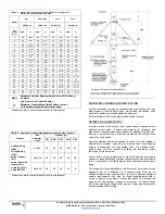
See Thermal Expansion Formula on page 3.
When assembled in any orientation, the amount of thermal expansion of the inner
pipe is directly dependent on the inner wall temperature and the length of pipe
between fixed points. Good installation practice requires that expansion greater
than 1/4 inch will be compensated for using a Bellows Joint or Adjustable Length,
depending on the maximum pressure encountered.
The flanged inner piping joints have negligible flexing capacity, and in addition, tees
and elbows are not designed to withstand bending moment forces. Because the
amount of outer casing axial movement is the same as inner casing movement, the
outer jackets of piping must slide to avoid excessive forces on Tees, Elbows of fixed
points. To accommodate outer casing movements, external guides along walls at
floors or in lateral breechings must allow for movement of pipe.
BELLOWS LENGTH
For exhaust pressure to 60 inches of water column, Bellows are recommended
for expansion and vibrational movements of the piping.
The Bellows has a 0.035” thick or heavier straight stainless steel liner to
protect the thinner spring material from heat and flow effects. It is used anywhere in
a system for axial and vibrational movements only and must be accurately
supported and guided. This part has limited lateral movement (1/8” max.) and
lateral offsets and parallel misalignments should be eliminated. The purpose of the
liner is to minimize contact, smooth flow, control erosion and eliminate resonance
caused by exhaust gases passing through the bellows.
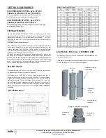
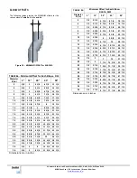
See Table 7 for Bellows
Properties
Typical Bellow design
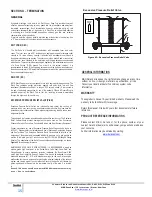
ADJUSTABLE LENGTH (LA) - EXPANSION JOINT
The
LA
has two functions. It is used to compensate for thermal expansion and
make up odd lengths of vent..
It is shipped with graphite band assembly preassembled on the sliding inner pipe.
The
LA
is adjustable from 7 1/4 to 28 3/8 inch.
See Figure 15
Figure
15
–
Adjustable
Length
(LA)
Gas
Flow
Cuttable
half
siding
outer
casing
Moveable
gasket
assembly
Cuttable
sliding
inner
wall
Spacing
Tool
supplied
Wrench
–
by
others

