background image

3


S

UBMITTAL


R

ECORD


FOR


D

URA

S

TACK


M

ODELS


DCL,


DAS1,


DIS1,


DIS2


AND


DIS4


M&G


D

URA

V

ENT


|


10


J

UPITER


L

ANE


|


A

LBANY

,


N

EW


Y

ORK


www.duravent.com


PRODUCT WEIGHTS


The average weight of the duct, per foot of length, can be estimated using the 
following formula:


DCL 0.40 X 

Diameter 

in 

inches 

= lbs per foot 

DAS1 0.79  X Diameter in 

inches


= lbs per foot


DIS1 0.93 X Diameter in 

inches


= lbs per foot


DIS2 1.09 X Diameter in 

inches


= lbs per foot


DIS4 1.44 X Diameter in 

inches


= lbs per foot


Chimney design should provide adequate support to ensure components are not 
overloaded.


THERMAL EXPANSION CALCULATIONS


Thermal expansion under normal operating temperatures can fatigue welds 
causing leakage. It is necessary to calculate the thermal expansion between two 
fixed points. 
 

Formula: [Length (ft) / 100] x [Temperature Rise degrees F / 100]  
Example

: [50’ / 100] x [75°F / 100] = 0.375” Expansion


If the computed expansions between the fixed points are greater than 0.375” -  
DuraVent recommends an adjustable or bellow length be installed.


SUPPORT METHODS AND HEIGHT LIMITS


1. 

Several support and guiding methods are used to anchor a chimney 
against upward,   downward and angular displacement.


2. 

These supports  and  guides  used with  thermal  expansion devices, 
prevent bending stresses on the chimney  elbows and joints.


3. 

Supports and guiding methods and installation  are described in 

SECTION  E-SUPPORTS

. Certain limitations  apply  for  proper 

installation of supports and guides. See 

Tables  3, 4 and  5 and 

Figures showing MVS and H.


4. 

It  is recommended to apply an exterior grade high heat paint to any 
plate supports,  full/half   angle  rings,  wall  supports/guides,  
aluminized   outer maximum   corrosion  protection   against  the  elements.  
(Ex: Rust-Oleum   V200 series High Heat Industrial Aerosol)


NOTE:  

All the weight  of the section is supported by the inner flue. 
Never support any chimney pipe from the outer casing.


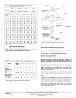
TABLE


3


Height


Limits


for


each


Type


of


Support


Parts


Flue


Diameter


Ø


(in)


HEIGHT


(ft)

DCL


DAS1


DIS1


DIS2


DIS4


Anchor


Plate


5


to


22


264

133


114


97

73

24


to


36


161

82


70


59

45

Anchor


Plate


with


Length


5


to


22


281

142


121


103

78

24


to


36


172

87


74


63

48

Base


Supported


Tee


5


to


22


102

52


44


37

28

24


to


36


63


32


27


23

17

Wall


Support


5


to


22


105

53


45


39

29

24


to


36


64


32


28


24

18

WARNING


Do


not


attach


any


supports


to


combustible


Dimensions are in inches (diameter) and feet (distance) 


Summary of Contents for DAS1 22 E30 CE

Page 1: ...INSULATED DIS1 1 INCH CERAMIC FIBER INSULATED DIS2 2 INCH CERAMIC FIBER INSULATED DIS4 4 INCH CERAMIC FIBER INSULATED DCL SINGLE WALL MATERIAL SELECTION FLUE INNER WALL CASING OUTER WALL 304 304 316...

Page 2: ...tent service at temperatures not exceeding 1800 F As such Model DAS PRO and D I S PRO Models are suitable for use with ovens and furnaces as described in the Chimney Selection Chart of NFPA No 211 in...

Page 3: ...d ceiling or floor above the hood through any concealed spaces to or through the roof to maintain the integrity of the fire separations required by the applicable building code provisions If the build...

Page 4: ...re used to anchor a chimney against upward downward and angular displacement 2 These supports and guides used with thermal expansion devices prevent bending stresses on the chimney elbows and joints 3...

Page 5: ...23 19 16 12 14 to 24 19 19 16 14 10 26 to 36 15 15 13 11 8 Dimensions are in inches diameter and feet distance EXTERIOR CORROSION PROTECTION It is recommended to apply an exterior grade high heat pain...

Page 6: ...F S 2000 is water soluble and should not be used where exposed to weather Part No S 375 Nuflex 302 General Purpose is a low temperature grey silicone 450 F only for weathering sealing on outdoor seams...

Page 7: ...band when assembled Figure 10 Joint Assembly Step 5 STEP 6 Secure the Outer Casing Band with the Outer Band BSE Joint installation is now completed NOTE For exterior installations it is recommended t...

Page 8: ...not designed to withstand bending moment forces Because the amount of outer casing axial movement is the same as inner casing movement the outer jackets of piping must slide to avoid excessive forces...

Page 9: ...IGHT LIMITS section Figure 17 T90 TEE PRECAUTION 1 Use an adjustable length in all horizontal breechings or laterals 2 If more than of thermal expansion is expected between the tee and the next fixed...

Page 10: ...ly as described in JOINT ASSEMBLY section Elbows are used in combination to make different angles ranging from 3 to 90 in horizontal and vertical segments of the duct system ELBOW 3 degree E3 Figure 2...

Page 11: ...8 11 7 8 32 1 4 26 3 8 2 5 8 6 7 8 12 1 2 34 1 4 28 3 8 2 3 4 7 1 8 13 36 1 4 30 3 8 2 3 4 7 3 8 13 5 8 38 1 4 32 3 8 2 7 8 7 5 8 14 1 8 40 1 4 34 3 8 3 8 14 3 4 42 1 4 36 3 8 3 8 1 4 15 3 8 44 1 4 D...

Page 12: ...ow DIS4 Diameter in 3 15 30 45 90 5 1 2 2 3 4 6 1 8 10 24 1 2 6 1 2 2 3 4 6 1 4 10 1 4 25 1 2 7 1 2 2 3 4 6 3 8 10 1 2 26 1 2 8 1 2 2 3 4 6 1 2 10 7 8 27 1 2 9 1 2 2 7 8 6 5 8 11 1 8 28 1 2 10 1 2 2 7...

Page 13: ...imum support the entire perimeter of the Plate Support must be attached to structural framing WARNING RISK OF FIRE DO NOT ATTACH THE PLATE SUPPORT TO COMBUSTIBLE CONSTRUCTION HEAVY DUTY WALL SUPPORT W...

Page 14: ...D HEAVY DUTY FLOOR GUIDE FGHD A Heavy Duty Floor Guide is similar in function to a Heavy Duty Wall Guide or Full Angle Ring but has been modified for use at floor penetrations The angle brackets and s...

Page 15: ...ration It can be supported by bracing with a Half Angle Ring HAR an Anchor Plate AP or an Anchor Plate Length APL SECTION F ROOF PENETRATION and FLASHINGS Flashing F The flat Roof Flashing F is used i...

Page 16: ...xhaust system backfire Engines have the potential to inject unburned fuel into an exhaust system during start up or due to an engine malfunction This unburned fuel creates a condition where a backfire...

Reviews: