background image

83

1 1 5 0 / 1 1 5 5   H A Y B U S T E R   T U B   G R I N D E R                     O P E R A T I N G   I N S T R U C T I O N S

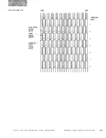
6.3  Troubleshooting Omnex Wireless Remote Controls

The OMNEX ORIGA is a portable, long range, programmable, 8‑channel radio remote control unit for 10 to 32VDC 

operated fixed and mobile equipment.  Designed as a safe, compact and easy‑to‑use radio remote control, the ORIGA 

puts complete control where it is needed most:  with the operator.

TROUBLESHOOTING THE OMNEX ORIGA

THE REMOTE RADIO CONTROLLER (T100)/TRANSMITTER

THE REMOTE RADIO RECEIVER (R100e)

Summary of Contents for Haybuster 1150

Page 1: ...ch Industries International Inc PO Box 1940 Jamestown ND 58402 1940 Tel 701 252 4601 Fax 701 252 0502 www duratechindustries net www haybuster com 1150 1155 Tub Grinder Manual 1 Operating Instructions TM Product Information TM ...

Page 2: ...A Tradition of Innovation Since 1966 ...

Page 3: ...time to time Even in the event of such updates you should still find this manual to be appropriate for the safe operation and maintenance of your unit This manual as well as materials provided by component suppliers to DuraTech are all considered to be part of the information package Every operator is required to read and understand these manuals and they should be located within easy access for p...

Page 4: ...A Tradition of Innovation Since 1966 ...

Page 5: ...important safety information Section 3 Machine operation which explains normal operation of the machine Section 3 1 Pre Operation Inspection Appropriate use of unit The 1150 1155 Haybuster Tub Grinders are designed to grind material into more palatable or manageable rations for your operation It has multiple uses 1 Grind most types of hay Big round bales Loose hay Square bales 2 Grind most types o...

Page 6: ...e screen sizes to get desired cut Operator protection As with all machinery care needs to be taken in order to insure the safety of the operator and those in the surrounding area WARNING The OPERATOR IS RESPONSIBLE for the safety of the operator and those in the surrounding area Operators and those observing the operation of the 1150 1155 Haybuster Tub Grinder are recommended to wear head eye and ...

Page 7: ...inguishers 18 1 11 Important safety reminders 19 1 12 Towing 19 Section 2 Introduction 20 2 1 Description of the 1150 1155 Haybuster Tub Grinders 20 2 2 Electronic governor 20 2 3 Fluid coupling 22 2 4 Rotor 22 2 5 Screens 22 2 6 Tub 23 2 7 Hydraulic cooler 23 2 8 Fluid coupler cooler 23 2 9 The conveyor system 23 2 10 Slug buster and Mill grate 23 2 11 1150 1155 Haybuster Tub Grinder Electronic E...

Page 8: ...rinder using the remote radio option 37 3 18 Grinding 39 3 19 Loading the tub 39 3 20 If lodging occurs while grinding 40 3 21 Grinding wet material 40 3 22 Preparing the 1150 1155 HAYBUSTER TUB GRINDER for transport 40 3 23 Preparing the 1150 1155 HAYBUSTER TUB GRINDER for operation after transport 42 3 24 Preparing the 1150 1155 HAYBUSTER TUB GRINDER for storage 42 3 25 Removing the 1150 1155 HA...

Page 9: ...rication 63 5 10 SKF Rotor bearing installation SN up to 0191 65 5 10a Dodge Rotor bearing installation SN 0192 up 69 5 11 Hammermill maintenance 73 5 12 Swinging hammer replacement and maintenance 74 Section 6 Troubleshooting the 1150 1155 HAYBUSTER TUB GRINDER 76 6 1 Troubleshooting the electronic governor system 76 6 2 General Troubleshooting 82 6 3 Troubleshooting Omnex Wireless Remote Control...

Page 10: ...vi T A B L E O F C O N T E N T S 1 1 5 0 1 1 5 5 H A Y B U S T E R T U B G R I N D E R O P E R A T I N G I N S T R U C T I O N S A Tradition of Innovation Since 1966 ...

Page 11: ...1 1 1 5 0 1 1 5 5 H A Y B U S T E R T U B G R I N D E R O P E R A T I N G I N S T R U C T I O N S 1150 1155 Tub Grinder Manual 1 Operating Instructions TM TM ...

Page 12: ...ional Inc DuraTech Industries representative before attempting to grind materials other than livestock forage Purpose The purpose of this owner s manual is to explain maintenance requirements and routine adjustments for the most efficient operation of your 1150 1155 Tub Grinder There is also a trouble shooting section that may help in case of problems in the field Any information not covered in th...

Page 13: ...to the customer it is the dealer s responsibility to conduct a training session on the safe operation of the unit for the primary operator s Dealer must also conduct a walk around inspection of all safety instructional decals on the machine itself Decals are illustrated in Manual 2 Parts Reference When dealer is satisfied that the primary operators have read the operating instructions and understa...

Page 14: ...ctions will function as a textbook during the dealer conducted training course that is required before use of the unit When all primary operators have read the operating instructions and understand all information concerning the safe operation of the unit the dealer will be required to sign the User Training Verification Form found in the 1150 1155 HAYBUSTER TUB GRINDER documentation packet NOTE T...

Page 15: ... to bring to our attention as quickly as possible any suggestions you may have concerning the safety of the equipment DuraTech Industries is dedicated to enhancing the safety of the DuraTech Industries 1150 1155 Haybuster Tub Grinder This unit is supplied with an operation and maintenance manual and this manual should be kept with the unit for periodic review by operational personnel Operators of ...

Page 16: ...ay result in mi nor or moderate injury It may also be used to alert against unsafe practices Safety Alert Symbol Read and recognize safety information Be alert to the potential for personal injury when you see this safety alert symbol 1 1 Safety alert symbols Decals are illustrated in Manual 2 Parts Reference The safety decals located on your machine contain important and useful information that w...

Page 17: ...ditions as stated in the text above Furthermore the text dealing with these situations is surrounded by a box with a white background will begin with DANGER WARNING or CAUTION The INFORMATION symbol is used to denote important information or notes in regards to maintenance and use of the machine The text for this information is surrounded by a box with a light grey background and will begin with e...

Page 18: ... doctor before operating Proper Clothing Clothing must be sturdy and snug fitting but allow complete freedom of movement Avoid loosefitting jackets scarfs neckties jewelry flared or cuffed pants unconfined long hair or anything that could become entangled with the machine Protect your hands with gloves when handling parts Heavyduty nonslip gloves improve your grip and protect your hands Good footi...

Page 19: ...RT HAZARD STAY OUT OF TUB WHEN ENGINE IS RUNNING 1 KEEP OTHERS AWAY 2 PLACE ALL CONTROLS IN NEUTRAL STOP ENGINE REMOVE KEY AND WAIT FOR ALL MOVING PART TO STOP BEFORE SERVICING ADJUSTING REPAIRING UNPLUGGING OR ENTERING THE TUB FOR ANY REASON 3 DISCONNECT DRIVELINE ON PTO MODELS DANGER ELECTROCUTION HAZARD TO PREVENT SERIOUS INJURY OR DEATH FROM ELECTROCUTION STAY AWAY FROM POWER LINES WHEN OPERAT...

Page 20: ...N OPERATION 5 KEEP HANDS FEET HAIR AND CLOTHING AWAY FROM MOVING PARTS 6 KEEP OTHERS AWAY FROM MACHINE WHILE IN OPERATION 7 INSTALL SAFETY LOCKS BEFORE TRANSPORTING OR WORKING BENEATH COMPONENTS 8 DO NOT ALLOW RIDERS AT ANY TIME 9 DO NOT LEAVE MACHINE UNATTENDED WHILE ENGINE IS RUNNING 10 KEEP ALL HYDRAULIC LINES COUPLINGS AND FITTINGS FREE OF LEAKS DURING OPERATION 11 KEEP AWAY FROM OVERHEAD ELEC...

Page 21: ...N THAT ALL PERSONNEL ARE CLEAR OF MACHINERY AREA 3 RAISE TUB TO FULL VERTICAL POSITION 4 STOP ENGINE AND REMOVE KEY BEFORE APPROACHING TUB AND ROTOR AREA WARNING HIGH PRESSURE FLUID HAZARD TO PREVENT SERIOUS INJURY OR DEATH RELIEVE PRESSURE ON SYSTEM BEFORE REPAIRING OR ADJUSTING OR DISCONNECTING WEAR PROPER HAND AND EYE PROTECTION WHEN SEARCHING FOR LEAKS USE WOOD OR CARDBOARD INSTEAD OF HANDS KE...

Page 22: ...NTIL ALL POTENTIAL FIRE DEBRIS IS REMOVED NO FIRE OR SMOLDERING EXISTS AND THE BATTERY IS SWITCHED OFF REMOVE ALL FLAMMABLE DEBRIS FROM ENGINE SHIELDING CONTROL PANEL UNDER MACHINE AND ANYWHERE MATERIAL IS COLLECTED DURATECH INDUSTRIES IS NOT RESPONSIBLE FOR FIRES CAUSED BY HAZARDS LEFT TO SMOLDER AND BURN OR IMPROPER SHUTDOWN PROCEDURES 6500425 DO NOT OPERATE MACHINE UNLESS AN APPROVED FIRE EXTIN...

Page 23: ...stems are in place that result in direct operator security Keep all foreign objects such as rocks pieces of metal and other incompressibles out of the tub and away from the mill Foreign objects may result in personnel injury or damage to the machine A foreign object is any object which the unit in not designed to grind Allow only responsible properly instructed individuals to operate machines Care...

Page 24: ...tor is at a complete stop and engine is shut down before any performing any maintenance Never grab rope cable twine or similar material hanging out of tub while the tub grinder is running Never enter the conveyor pivot area when the engine is running WARNING Loose clothing necklaces and similar items are easily caught in moving parts Avoid the use of these items if possible Keep long hair confined...

Page 25: ...and persons in the area Keep all observers away from the machine Dimensioning the size of this area is not practical The distance a thrown object may travel is dependent on several conditions including but not limited to rotor speed and diameter condition of the hammers style of hammers object mass object shape amount of material in the tub and how the hammer strikes the object Figure 1 1 Figure 1...

Page 26: ...id coupler has been disengaged Before performing any maintenance on the machine or getting into the tub be sure rotor and all moving parts have come to a complete stop Shut off engine and remove the key Before working on or near the Tub Grinder for any reason such as servicing inspecting or unclogging the machine Follow the normal shutdown procedure found on page 28 of this manual If the unit is s...

Page 27: ...might occur during normal grinding operations Keeping the material moving through the machine and across the top of the rotor is important to keep frictional heating of the material to a minimum IMPORTANT NEVER leave the vicinity of the unit with the engine running PROPER OPERATION OF THE TUB GRINDER Do not grind materials any finer than necessary Finely ground materials will produce more dust and...

Page 28: ...the rapid spreading of a fire once it has begun Inspect all electrical wiring periodically Any chafed or damaged wires should be repaired immediately Keep all electrical connections tight to prevent arcs or sparks Contact between the rotor and any stationary component of the grinding chamber such as contact between the hammers and the screens must be corrected immediately 1 10 Fire Extinguishers F...

Page 29: ...de loads on public roads and other possible requirements Use caution when traveling on public roads rough or winding roads or steep terrain See Section 3 22 for more information about preparing the unit for transport Read the label on your extinguisher now most extinguishers have descriptions of this method and an estimated working time If an extinguisher is only partially used the dry chemical wi...

Page 30: ...ic governor has two modes of operation the Engine Auto mode and the Tub Manual mode The Engine Auto mode is the preferred mode of operation and should be used whenever possible Engine Auto Mode When the electronic governor is switched to the Engine Auto mode it is monitoring the rotation speed of the engine The hydraulic flow to the tub drive mechanism is regulated proportionally to the engine spe...

Page 31: ...access panel battery box discharge conveyor in the transport position optional hay guide in the transport position tub drive access panel and shield tub roller access panel and shield figures 2 2 2 3 major system components folding tub flare fire extinguisher folding tub flare in the folded position rear conveyor controls optional screen rack fluid coupling cooler ...

Page 32: ... when the rotor stops spinning 2 4 Rotor The rotor is the heart of the grinder The standard rotor contains swinging hammers and is used for general grinding 2 5 Screens All DuraTech Industries tub grinders come equipped from the factory with two screens The diameter of the screens are specified by the customer at the time of purchase Any combination of hole sizes may be used to alter the coarsenes...

Page 33: ...se hay use two tub fins bolted in the lower position 2 7 Hydraulic cooler The hydraulic system has a radiator to disperse excess heat It is mounted in front of the engine radiator and can be accessed via the radiator access panel 2 8 Fluid coupler cooler The fluid coupler system has a radiator and fan to dissipate excess heat A thermostat will start the fan whenever the hydraulic oil going into th...

Page 34: ...Conveyor Up Down Conveyor pivot Right Left Remote radio Local switch Tub rotation Forward Reverse Conveyor On Off Engine kill switch red in color Throttle toggle Optional hay guide Scroll switch 2 11 1 Control panel The control panel is located on the left hand side of the en gine Controls on the control panel include engine start emergency kill switch throttle tub controls conveyor on off conveyo...

Page 35: ...d in for approximately 30 seconds Rotor disengage button push in to disengage fluid coupler yellow in color Electronic governor Rotor status lights Grinding hours gauge Job hours gauge Job hours reset button See Section 2 11c Conveyor Run Remote Radio Cab Panel Optional Tub Cover In Out Down Up Tub Forward Reverse Conveyor Up Down Right Left Lights On Off Screen On Off Jacks Left Right Up Down For...

Page 36: ...r III Fuel gauge Rotor engage button hold in for approximately 30 seconds Rotor disengage button push in to disengage fluid coupler yellow in color Electronic governor Rotor status lights Grinding hours gauge Job hours gauge Job hours reset button See Section 2 11c Remote Radio Panel Switch Cab Work Light Panel Light Tub Screen Up Down Tub Forward Reverse Conveyor Up Down Fold Unfold Lights On Off...

Page 37: ... Tier II and Tier III Engines Service tool connector Engine kill switch red in color 5700861 Throttle control 5700497 Key switch 5700907 Engine tachometer 5700940 Voltmeter Warning lamp 5700941 Water temperature Maintenance lamp Maintenance clear switch Circuit breaker 5700938 Fuel pressure Diagnostic lamp 5700939 Oil pressure ...

Page 38: ...h allows the operator to pivot the conveyor left and right Radio remote control unit optional The optional radio remote control unit allows the operator to remotely start and stop the tub change the tub s direction of rotation to forward or reverse perform an emergency stop raise and lower the conveyor and swing the conveyor left and right NOTE See also section 3 17 Operating the grinder using the...

Page 39: ...l level and add or change the hydraulic oil as necessary Also look for leaks in the hydraulic system q Check the air cleaner service indicator If the red indicator is visible service the air cleaner q Check for buildup of debris around the radiator turbocharger manifolds air intake and moving parts Remove the debris before operating the unit q Inspect belts for cracks breaks or other damage q Insp...

Page 40: ...e The engine should run smoothly at low idle 7 Make another walk around inspection checking the engine and hydraulic system for fluid leaks 8 Follow the engine manufacturers recommendations for the care and maintenance of a new engine NOTE See also section 3 17 Operating the grinder using the remote radio option 3 3 If the engine fails to start If the engine doesn t start on the first try perform ...

Page 41: ...generally this consists of running the engine at 1 2 speed or idle for 5 minutes 6 Shut off the engine and remove the key 7 Never leave the machine unattended until any potential fire debris is removed no fire or smoldering exists and batterry is switched off 8 Turn the battery disconnect switch to OFF 9 Note the service hour meter reading and perform periodic maintenance as required 10 Repair any...

Page 42: ... off and two other positions which correspond to the tub manual and engine auto modes of operation In the tub manual position the tub will rotate at a constant speed based on the settings of the Tub Limit Knob Tub Speed Knob The engine auto position uses all the functions of the Electronic Governor The maximum tub speed will be limited by the Tub Limit Knob Tub Speed Knob and the engine load will ...

Page 43: ...ws the electronic governor to automatically control the feed rate keeping the engine running within the governor s optimum power zone When the load on the grinding rotor begins to lug the engine the governor automatically reduces the tub s rotation speed in proportion to the load The result is nearly a constant load on the engine which maximizes the grinding efficiency The range of rotor speeds fo...

Page 44: ...ture throttle the engine to under 1500 RPM Engage the rotor and tub drive then throttle up to 1800 RPM The FUSE light and the SENSOR light should come on The tub should not be rotating at this time If the tub is rotating read section 6 1 Troubleshooting the electronic governor system in this manual 5 Slowly rotate the ENGINE LOAD KNOB counter clockwise until the tub just begins to move The tub sho...

Page 45: ...perator station control panel is lit the tub will not raise If the green tub interlock indicator on the operator station control panel is lit the tub may be raised 6 Raise the tub fully and install the safety stop on the hydraulic cylinder The safety stop is located in its storage location on the inside of frame rail NOTE The tub will not lift if the rotor is turning Also when the tub is raised th...

Page 46: ...ischarge conveyor The discharge conveyor can be raised or lowered as needed There are two sets of controls for raising and lowering the conveyor One set of controls is at the operator panel and one set is at the rear left of the machine NOTE See also section 3 17 Operating the grinder using the remote radio option 3 16 Pivoting the discharge conveyor The conveyor can be swung left or right as need...

Page 47: ...operation this LED is flashing The red LED indicator is located on the upper left hand side of the radio transmitter This LED flashes slowly to indicate the transmitter has less than twenty percent of bat tery capacity remaining When both the red and yellow LEDs are on the transmitter is in configuration program mode Mode of operation The Omnex Origa system has several modes of operation The mode ...

Page 48: ...r conveyor swing For more information on using and troubleshooting the Omnex Origa system please refer to Section 6 3 Troubleshooting the Omnex Wireless Remote Controls which starts on page 69 Remote radio start up To begin using the remote radio perform the following steps 1 Press the green power on button on the transmitter The yellow LED should start flasing to indicate that the transmitter is ...

Page 49: ... it to the desired height 3 Engage the conveyor run switch to the forward position 4 Engage the fluid coupler by pulling the rotor disengage button out and pressing the rotor engage button in and holding it until the rotor is spinning approximately 30 seconds 3 19 Loading the tub IMPORTANT Never drop a large object or objects into the tub from a high level Ease the material over the edge and down ...

Page 50: ... transport over public roads perform the following steps 1 Be sure all loose parts such as screens hammer rods or extra hammers are properly stowed 2 If the machine has folding flares rotate the tub so the folding flares line up with the side of the machine 3 Fold the discharge conveyor and then raise the discharge conveyor into the transport position which is shown in figure 3 2 on the following ...

Page 51: ...nsport position 7 Check the lights and the brakes for proper function 8 If your machine is a model 1155 tub grinder check the turning clearance between the grinder and the towing vehicle 9 Check local ordinances regarding restrictions for machine travel on local roads Read Section 1 12 Towing in the Safety section in this manual ...

Page 52: ...e top section of the discharge conveyor until it is fully extended When unfolding the conveyor do not exceed an engine speed of 1000 RPM Excessive engine RPM will cause the conveyor to fold too fast and may cause damage 7 Raise the conveyor to operating height 3 24 Preparing the 1150 1155 HAYBUSTER TUB GRINDER for storage To prepare the 1150 1155 HAYBUSTER TUB GRINDER for storage perform the follo...

Page 53: ...r weight to lift them free of the grinder 5 Use only pry bars to guide the screens in and out of the machine The screens are very heavy and could easily cause injury if the screen moves suddenly or is inadvertently dropped 6 Clear all material from the screen track before installing a new screen 7 Install the new screen using the lifting device and pry bars as explained above 8 Make certain that t...

Page 54: ... belt adjusting bolts figure 3 3 belly conveyor belt adjusting bolt adjustment bolts Both rollers on the belly conveyor and the discharge conveyor are adjustable to allow for belt stretch and tracking If the conveyor belt slows down or stops during operation slippage may be the cause To eliminate slippage tighten the adjusting bolts on the conveyor equally This will increase the conveyor belt s te...

Page 55: ... 4 If further adjustment is required disengage hydraulic conveyor drive switch and shut down the machine using the normal shutdown procedure 5 Some adjustment of the drive roller may be required if no improvement is noted by adjusting the idler roller tension 6 Repeat steps 1 5 until proper tracking is achieved C If the belt is running to the left side perform the following steps 1 Adjust the idle...

Page 56: ...s to be flipped around or replaced When the poly blades wear to within 1 8 of the scraper frame and doubler either flip the poly blade around or replace with a new one Note the belt scrapers are located inside the belt 1 Always make sure the belt seals pn 1700166 and endless belt are in contact with each another 2 When adjusting the belt seal as it wears down loosen the bolts and push belt seal do...

Page 57: ...n be set to any rpm but the recommended rpm is 1500 2000 3 Pull the yellow rotor disengage button out 4 Press and hold the rotor start button until the rotor is spinning This will take approximately 30 seconds 3 33 Disengaging the fluid coupler To disengage the fluid coupler perform the following steps 1 Empty the tub 2 Push rotor disengage button in 3 31 Adjusting tub chain tension To adjust the ...

Page 58: ...e resistance should be between 38 to 44 ohms If the values are not within this range replace the electro hydraulic valve coil MANUAL OVERRIDE NOTE If there is an electrical failure with the machine it may still be able to grind Switch the electronic governor off Remove the rubber end cap and loosen the jam nut on the electro hydraulic valve Start the machine and engage the tub drive figure 3 5 loc...

Page 59: ...g parts while calibrating the electro hydraulic valve The tub will be rotating during this adjustment To calibrate the electro hydraulic valve coil after following the three steps above perform the following steps 1 Remove the rubber end cap from the end of the electro hydraulic valve This will reveal a jam nut and an adjusting stud with a screwdriver slot 2 Disconnect the wiring harness from the ...

Page 60: ...shutdown procedure in this manual 2 Disconnect the wiring harness from the electro hydraulic valve coil 3 Remove the acorn nut from the end of the electro hydraulic valve This will reveal a jam nut and a adjusting stud with a screwdriver slot 4 Loosen the jam nut 5 Turn the adjusting screw counterclockwise until it stops 6 Lock the adjusting screw with the jam nut and replace the acorn nut Reconne...

Page 61: ...curring in the tub Stabilizer legs are included with the optional loader and their controls are located in the operator s cab with the controls for operating the loader The stabilizer legs stabilize the loader during operation engine rpm guage oil pressure guage water temperature guage engine warning light electronic governor control engine throttle control conveyor start stop control left right o...

Page 62: ...Boom Raise Knuckle Lower Knuckle Raise Right Hand Joystick Controls Left Hand Joystick Controls left hand joystick left hand switch right hand joystick right hand switch Right hand switch controls the Swing left Swing Right of the Discharge conveyor Left hand switch controls the Up Down of the discharge conveyor Foot Controls for 1150 1155 Grapple Loader rotates boom left rotates boom right ...

Page 63: ...tenance manual for the engine 5 1 Welding Procedure Welding on a machine that is equipped with an Electronic Engine Proper welding procedures are necessary in order to avoid damage to the computerized equipment Computerized equipment includes but is not limited to the following the Engine Control Module ECM electronic governor HPTO Control Module if equipped Omnex Radio Receiver if equipped and AB...

Page 64: ...ector pins 4 Connect the welding ground cable directly to the part that will be welded Place the ground cable as close as possible to the weld in order to reduce the possibility of welding current damage to the bearings hy draulic components electrical components and ground straps NOTE If the electrical electronic components are used as a ground for the welder or electrical electronic components a...

Page 65: ...nd water should contain as much grease as speed will permit At higher speed ranges too much grease will cause the bearings to overheat Abnormal bearing temperature during high speed operation may indicate faulty lubrication The normal temperature may range from cool to warm to the touch If a bearing is too hot to touch for more than a few seconds and the bearing is leaking grease excessively there...

Page 66: ...56 1 1 5 0 1 1 5 5 H A Y B U S T E R T U B G R I N D E R O P E R A T I N G I N S T R U C T I O N S LUBRICATION CHART ...

Page 67: ... S T E R T U B G R I N D E R O P E R A T I N G I N S T R U C T I O N S figure 5 2 rotor bearing vent and sight glass rotor bearing sight Ref 1 lubrication zerk Ref 6 lubrication zerk Ref 6 figure 5 3 drive line lubrication points ...

Page 68: ...ge conveyor lift and discharge conveyor pivot lubrication points lubrication zerks discharge conveyor pivot Ref 9 figure 5 5 belly conveyor roller discharge conveyor roller lubrication points belly conveyor roller Ref 11 discharge conveyor lift pivot Ref 10 belly conveyor roller Ref 11 discharge conveyor roller Ref 8 ...

Page 69: ...R O P E R A T I N G I N S T R U C T I O N S figure 5 6 discharge conveyor roller lubrication point discharge conveyor roller Ref 8 figure 5 7 tub pivot lubrication points tub pivots Ref 12 figure 5 8 radiator pivot lubrication points radiator pivots Ref 17 ...

Page 70: ...nterline of the bottom roller The oil level in the sight glass should be centered in the sight glass When adding or replacing rotor bearing oil use Mobil SHC 626 oil or other similar oil but never use a detergent motor oil Tub Pressure Roller lubrication point Ref 16 rotor bearing sight glass 5 5a Rotor bearing lubrication Dodge Imperial ISAF Bearing lubrication SN up to 0191 SN 0192 up Imperial s...

Page 71: ...500 hours and change hydraulic oil and filters at least every 1000 hours of operation Change the in tank oil filter if the oil filter pressure gauge indicates a plugged filter Check the hydraulic oil regularly and if the oil has a burnt smell or milky appearance change it immediately hydraulic reservoir hydraulic oil temperature gauge hydraulic oil fill cap oil filter pressure gauge DuraTech Indus...

Page 72: ...fter the fluid coupler is disconnected If it is close to the trip point high oil temperature may be the problem If the temperature gauge needle is not close to the trip point high oil pressure may be the problem Change the fluid coupler oil filter 4400087 when the pressure reading is within 5 psi of the trip point or when the fluid coupler is disengaged due to high oil pressure There are two model...

Page 73: ...tion method assures long bearing life with proper maintenance of the oil level When adding or replacing oil in the wheel bearings use SAE 80W 90 HYPOID GEAR OIL AIR BRAKES The air brakes should be inspected periodically by a qualified air brake technician CAUTION Care must be exercised when lubricating the camshaft bushings and anchor pins Over lubrication could cause a safety problem as brake lin...

Page 74: ...30 000 miles Check lining wear and estimate reline time Inspect camshaft camshaft spider bushing and camshaft support bracket bushing for any signs of wear Lubricate brake actuating components Every 100 000 miles once a year or at brake reline Replace wheel bearing lubricating oil if applicable Check brake air chambers and slack adjusters Inspect brake rollers roller shafts anchor pins and bushing...

Page 75: ...y require slight hand pressure to overcome The O ring can be lubricated with grease or oil to ease assembly Locate the seal to match the Labyrinths in the housing The picture shows the PosiTrac Plus seal which requires greasing the seal lip at assembly Note the orientation of the seal one way prevents oil leakage the other way prevents dirt from entering the bearing Assemble the seat to prevent di...

Page 76: ... Wipe the preservative from the bore of the bearing and then oil the surface light Use a thin mineral oil e Measure the unmounted internal radial clearance in the bearing by inserting progressively larger feeler blades the full length of the roller between the most vertical unloaded roller and the outer sphere Write this number down f Place the bearing on the sleeve Screw the nut with its chamfere...

Page 77: ... step e i Unscrew the nut placing the lock washer in position and tighten the nut firmly again Make sure that the bearing is not driven up the sleeve any further j Lock the nut by bending on e of the lock washer tabs down into one of the slots in the nut Do not bend it to the bottom of the slot k Check that the shaft or bearing can be turned easily by hand 4 Install outboard seal Again watch orien...

Page 78: ...outer race On both bearings move the shaft axially so that the stabilizing ring can be inserted between the bearing outer race and housing shoulder on the locknut side of the bearing 7 The bearing seat on the upper half of the housing cap should be checked for burrs thoroughly cleaned lightly oiled and placed over the bearing With oil lubrication use a sealing compound such as Permatex 2 or equiva...

Page 79: ...dures be followed Products must be used in accordance with the engineering information specified in the catalog Proper installation maintenance and operation procedures must be observed The instructions in the instruction manuals must be followed Inspections should be made as necessary to assure safe operation under prevailing conditions Proper guards and other suitable safety devices or procedure...

Page 80: ...ed as the point when the clearance between adapter sleeve shaft and bearing bore has been removed and all surfaces are in metal to metal contact 3A To reach the ZERO Reference Point rotate locknut clockwise using both hands as tight as possible When mounting bearings with shaft sizes 3 15 16 and larger the following TEST must be performed As a test to insure you have reached the ZERO Reference Poi...

Page 81: ...nut hole that aligns with a lockplate hole If the closest locknut hole is beyond a lockplate hole then tighten not loosen the locknut to meet a lockplate hole c Insert lockwasher and tighten button head screws to lock assembly Ref Picture 4 6 Bolt down pillow block or flange unit to the structure EXPANSION Pillow Blocks Locknut facing outboard Align pillow block housing mounting holes with substru...

Page 82: ... DISMOUNTING 1 Remove weight off bearing via a sling or jacks 2 Remove mounting bolts from bearing 3 Remove button head screws and lockplate from the adapter nut 4 Using a spanner wrench turn the locknut counterclockwise until the bearing unit is Pushed off the adapter sleeve sufficiently to permit the release of the adapter sleeve from the shaft TABLE 2 Cap Bolt Torque for ISAF Pillow Blocks Non ...

Page 83: ... can be turned end for end exposing the new cutting edges The results of badly worn hammers and screens is loss of capacity and added horse power requirements WARNING The hammers have been heat treated and any alteration of the hammers by heating grinding resurfacing or any other process can change the mechanical properties of the hammer and make it unsuitable or dangerous to use The hammers are d...

Page 84: ...f the mill Determine the cause and correct it before starting the mill again To replace worn hammers on machines with swinging hammers perform the following steps 1 Follow the normal shutdown procedure which can be found on page 28 of this manual 2 Loosen the four bolts at the front of the rotor which holds the hammer rod retainer plate in place 3 Rotate the retainer plate to align holes allowing ...

Page 85: ...75 1 1 5 0 1 1 5 5 H A Y B U S T E R T U B G R I N D E R O P E R A T I N G I N S T R U C T I O N S hammer spacing chart ...

Page 86: ...peration of the electronic governor With the engine and hydraulic systems at operating temperature and the tub drive control valve in the forward position throttle the engine up to 1800 2000 RPM With the mode switch in the tub position the tub should be rotating The speed of the tub can be varied by rotating the tub limit knob The number of tub speed lights which are lit will vary with the setting...

Page 87: ...ontrols function correctly after following the tub mode trouble shooting check list then follow the calibration instructions on page 31 of this manual If the tub will not rotate proceed to trouble shooting table 6 2 Table 6 2 Troubleshooting the electronic governor s engine mode Sensor Test The gap between Sensor and Sprocket tooth is 3 32 2 4 mm Sensor resistance is 900 ohms 10 ...

Page 88: ...the valve With a voltmeter set for 12 volts DC connect the red lead of the voltmeter to the red lead of the wiring harness and black lead to the black wire Turn the tub limit knob until the left speed light turtle is on The voltmeter should read approximately 6 volts Turn the tub limit knob clockwise As more speed lights light up the voltage should increase Turn the knob until the right speed ligh...

Page 89: ...rnor off Remove the rubber end cap and loosen the jam nut on the electro hydraulic valve Start the machine and engage the tub drive figure 6 1 electronic governor system IMPORTANT DO NOT ENGAGE THE FLUID COUPLER AT THIS TIME Turn the adjusting stud clockwise until the tub rotates at the desired speed Lock the jam nut on the adjusting stud and replace the rubber end cap on the electro hydraulic val...

Page 90: ... the valve With a voltmeter set for 24 volts DC connect the red lead of the voltmeter to the red lead of the wiring harness and black lead to the black wire Turn the tub limit knob until the left speed light turtle is on The voltmeter should read approximately 6 volts Turn the tub limit knob clockwise As more speed lights light up the voltage should increase Turn the knob until the right speed lig...

Page 91: ...ernor off Remove the rubber end cap and loosen the jam nut on the electro hydraulic valve Start the machine and engage the tub drive figure 6 3 electronic governor system IMPORTANT DO NOT ENGAGE THE FLUID COUPLER AT THIS TIME Turn the adjusting stud clockwise until the tub rotates at the desired speed Lock the jam nut on the adjusting stud and replace the rubber end cap on the electro hydraulic va...

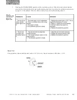
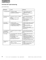
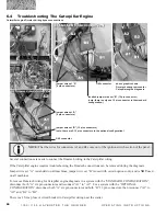
Page 92: ...82 1 1 5 0 1 1 5 5 H A Y B U S T E R T U B G R I N D E R O P E R A T I N G I N S T R U C T I O N S 6 2 General Troubleshooting general troubleshooting ...

Page 93: ... a portable long range programmable 8 channel radio remote control unit for 10 to 32VDC operated fixed and mobile equipment Designed as a safe compact and easy to use radio remote control the ORIGA puts complete control where it is needed most with the operator TROUBLESHOOTING THE OMNEX ORIGA THE REMOTE RADIO CONTROLLER T100 TRANSMITTER THE REMOTE RADIO RECEIVER R100e ...

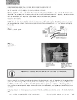
Page 94: ...SETUP button The R100E is now ready to receive the programming information from the T100 Transmitter 6 Press and release the GREEN Power Button on the T100 to start sending the Programming information to the R100E Receiver The Green Link LED on the R100E Receiver will begin to flash and the Green Status LED on the R100E Receiver will be ON steady Wait for the Link LED to stop flashing for the Stat...

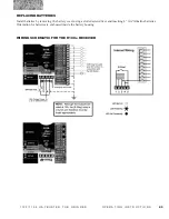
Page 95: ... I N G I N S T R U C T I O N S REPLACING BATTERIES Install batteries by removing the battery cover using a slotted screwdriver and inserting 4 AA Alkaline batteries Orientation for batteries is embossed inside the battery housing WIRING SCHEMATIC FOR THE R100e RECEIVER ...

Page 96: ...ith certain options only and is NOT used on all machines To remove Duratech wiring for Catepillar engine diagnosis in a system with the STANDARD CONFIGURATION disconnect both A six pin connectors and reconnect A1 to A2 For a system with the OPTIONAL CONFIGURATION disconnect both A six pin connectors and both B 12 pin connectors then reconnect A1 to A2 and B1 to B2 There is a 15 Amp fuse or circuit...

Page 97: ...ine One connector is used to connect the DuraTech wiring harness to the Caterpillar wiring If the Caterpillar engine requires troubleshooting the DuraTech connection can be removed during the diagnosis To remove the DuraTech wiring for Caterpillar engine diagnoses disconnect connection A There is a 15 Amp fuse or circuit breaker in the Caterpillar wiring harness near the starter Connection A ...

Page 98: ...is warranty does not apply to tires bearings batteries engines or any other trade accessories not manufactured by DuraTech Industries International Inc Buyer must rely solely on the existing warranty if any of these respective manufacturers DuraTech Industries International Inc shall not be held liable for damages of any kind direct contingent or consequential to property under this warranty DuraT...

Page 99: ...89 1 1 5 0 1 1 5 5 H A Y B U S T E R T U B G R I N D E R O P E R A T I N G I N S T R U C T I O N S A Tradition of Innovation Since 1966 ...

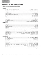
Page 100: ...r at base 9 274 cm Tub Wall 12 gauge Tub Floor 1 4 0 635 cm thick Tub Drive Single hydraulic orbit motor direct drive chain Service Access 90 hydraulic tilting tub Discharge Conveyor 26 792 cm l x 24 732 cm w hydraulic end driven cleated belt Belly Conveyor 30 76 cm wide hydraulic end driven cleated belt Tub Speed Sensor Electronic self governing Hammermill Hammer Size 1 2 1 27 cm A B hammers Roto...

Page 101: ...epth 50 127 cm Tub Diameter at base 9 274 cm Tub Wall 12 gauge Tub Floor 1 4 0 635 cm thick Tub Drive Single hydraulic orbit motor direct drive chain Service Access 90 hydraulic tilting tub Discharge Conveyor 26 792 cm l x 24 732 cm w hydraulic end driven cleated belt Belly Conveyor 30 76 cm wide hydraulic end driven cleated belt Tub Speed Sensor Electronic self governing Hammermill Hammer Size 1 ...

Page 102: ...B U S T E R T U B G R I N D E R O P E R A T I N G I N S T R U C T I O N S Options Radio remote that features the following commands tub start stop tub forward reverse conveyor up down and emergency stop Air Compressor Hay Guide ...

Page 103: ...S T R U C T I O N S Appendix C Operator Training Form The following personnel by their signature certify that they have read this manual in its entirety and comprehend its instructions Only personnel so qualified are allowed to operate this unit Printed Name Review Date Signature ...

Page 104: ...94 1 1 5 0 1 1 5 5 H A Y B U S T E R T U B G R I N D E R O P E R A T I N G I N S T R U C T I O N S A Tradition of Innovation Since 1966 ...

Page 105: ..._______________________ _ _________________________________________________________________________ _ _________________________________________________________________________ _ _________________________________________________________________________ _ _________________________________________________________________________ _ ______________________________________________________________________...

Page 106: ...96 1 1 5 0 1 1 5 5 H A Y B U S T E R T U B G R I N D E R O P E R A T I N G I N S T R U C T I O N S A Tradition of Innovation Since 1966 ...

Reviews: