background image

DUPLOMATIC                    E.M.DDC4-400V/RK  RELEASE 1.9 07-09 

EM DDC4-400-RK-0709gb.doc 


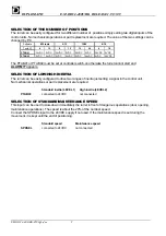
SELECTION OF THE NUMBER OF POSITIONS 

The turret can be easily configured for two different number of  positions simply setting two digital inputs of the 
control units. No mechanical operations or part replacement are required. The value of the two settings can be 
changed by PC.  

Software 

8/12 

tools 

6/12 12/24 8/16 

Tools N° 

8 12 6 12 12 24 8 16 

PTAB01 

24VDC 0VDC 


24VDC 0VDC 


24VDC 0VDC 


24VDC 0VDC 


PTAB02 

0VDC 24VDC 

0VDC 24VDC 

0VDC 24VDC 

0VDC 24VDC 

 
The PTAB01 or PTAB02 must be set at controller switch-on otherwise the turret cannot start and  

ALARM 77

 appears.  

SELECTION OF LOW/HIGH INERTIA 

The turret can be easily configured to drive two ranges of inertia just setting a signal in the control unit. 
No mechanical operations or part replacement are required  


Standard inertia (LEVEL 1) 

High inertia (LEVEL 2) 

PTAB03 

connected to 24VDC 

not connected


SELECTION OF STANDARD/MAINTENANCE SPEED 

This input can be used to slow-down immediately the turret in front of dangerous operations (door opening, 
maintenance operations). The speed is about the 20% of the nominal speed. 
Connect the SPDSEL input to the 24VDC supply if not used. If the maintenance speed is set during the 
movement, it is kept until the end of positioning. 


Standard speed 

Maintenance speed 

SPDSEL 

connected to 24VDC 

not connected


Summary of Contents for DDC4-10-400/20

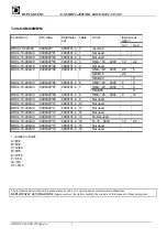
Page 1: ...496322 03 0489100 4 3 SM 16 400V 1 2 2 2 DDC4 10 400 20 0496322 04 0489100 4 4 Not used DDC4 10 400 20 0496322 05 0489100 4 5 SM 20 400V 3 5 DDC4 10 400 20 0496322 06 0489100 4 6 SM 20 400V 5 9 DDC4 10 400 20 0496322 07 0489100 4 7 SM 25 400V 5 9 DDC4 10 400 20 0496322 08 0489100 4 8 SM 25 400V 9 14 DDC4 10 400 20 0496322 09 0489100 4 9 Not used DDC4 10 400 20 0496322 10 0489100 4 10 Not used DDC4...

Page 2: ...00 20 0496320 07 0489101 4 7 SM B25 9 DDC4 15 400 20 0496320 08 0489101 4 8 SMA 25 400V 9 14 DDC4 15 400 20 0496320 09 0489101 4 9 Not used DDC4 15 400 20 0496320 10 0489101 4 10 Not used DDC4 15 400 20 0496320 11 0489101 4 11 Not used DDC4 15 400 20 0496320 12 0489101 4 12 Not used DDC4 15 400 20 0496320 13 0489101 4 13 No Not used DDC4 15 400 20 0496320 14 0489101 4 14 FL 16 400V 1 4 2 5 DDC4 15...

Page 3: ...9 SELECTION OF LOW HIGH INERTIA 9 SELECTION OF STANDARD MAINTENANCE SPEED 9 3 INTERFACING TO CNC 10 OPERATING FUNCTIONS 10 ZERO SEARCH 10 OPERATING FUNCTIONS DESCRIPTION 11 OPERATING FUNCTION N 0 EMERGENCY RESET 13 OPERATING FUNCTION N 1 2 3 AUTOMATIC 13 OPERATING FUNCTION N 4 JOG 14 OPERATING FUNCTION N 5 SERVICE 14 OPERATING FUNCTION N 7 SAFETY 15 4 DIAGNOSTIC 17 ALARMS AND WARNINGS 17 EXTENDED ...

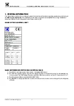
Page 4: ...Model DDC4 10 400 20 Code 0496320A03 S N DSP FW 2 4 I O FW 5 TABLE SET 0489100 TABLE SELECT 3 SM16 INERTI A LEV 1 LEV 2 J kgm2 1 2 2 2 PTAB03 24V 0V TOOLS 8 12 PTAB01 24V 0V PTAB02 0V 24V MAIN DIFFERENCES WITH DDC2 CONTROL RACK 1 New DDC4 controller inside more robust full digital DSP driven 2 No 230V AC auxiliary supply only 24V DC supply required Connector X5 is kept for compatibility but no mor...

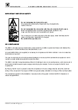
Page 5: ... CEI EN 61800 2 and CEI EN 61800 3 A11 An external EMC filter non supplied is necessary for compliance whet DDC controller turret are tested as stand alone component The use in civil environment could generate disturbance to some electrical and electronic equipment and it needs to provide additional solutions to avoid this effect The DDC4 controller being transistorised drive for brushless motor i...

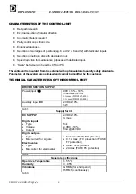
Page 6: ...ators to satisfy safety standards Parameters of the system are optimised and cannot be modified by the customer TECHNICAL CARACTERISTICS OF THE CONTROL UNIT DRIVER SECTION SUPPLY Power input 3 Φ 400V 15 10 50 60Hz 2Hz 3 Φ 18 A max DDC4 15 400 10 A max DDC4 10 400 Auxiliary input DC 24V DC 10 35W tab 1 Supply for I O DC SUPPLY 24V DC 10 3A max Digital inputs Type Voltage Current Sink 24 VDC 10 5 mA...

Page 7: ...s an external 24V DC supply CM1 to build up all auxiliary supply necessary for the driver section And I O to CNC An external slow type fuse of 1 A must be used to protect this supply POWER SUPPLY 24VDC FOR ELECTROVALVES see tab 2 The electrovalve s are operated by relays inside RACK requiring a second 24 V DC source on CM2 The max current consumption is related on the load on its outputs and is ab...

Page 8: ...O I O PBIT01 PBIT02 PBIT04 PBIT08 PBIT16 position code bits PARITY parity for position codes PSTART signal for starting turret cycle MODE01 MODE02 MODE03 mode select code bits SPDSEL selection of standard or maintenance speed INPUTS FROM TURRET TO DRIVER LOCKSW turret locked switch ULCKSW turret unlocked switch rotation free ZEROSW turret reference switch home switch MOTOVL thermal detector switch...

Page 9: ...otherwise the turret cannot start and ALARM 77 appears SELECTION OF LOW HIGH INERTIA The turret can be easily configured to drive two ranges of inertia just setting a signal in the control unit No mechanical operations or part replacement are required Standard inertia LEVEL 1 High inertia LEVEL 2 PTAB03 connected to 24VDC not connected SELECTION OF STANDARD MAINTENANCE SPEED This input can be used...

Page 10: ...ret will always use the CCW direction path to reach the position required 4 Jog next tool in CW or CCW 0 0 1 The turret will reach the next position 5 Service 1 0 1 Enables a series of functionality to simplify the start up phase and troubleshooting 6 RESERVED 7 Safety 1 1 1 Enables a series of functionality to overcome conditions that normally would stop the turret for a long time ZERO SEARCH Aft...

Page 11: ...e turret can work It is possible to make a cross check among the current position and the called one because all signals are stable Position bits and parity bit must be stable for at least 30 ms from PSTART signal After this time and once the turret confirmed the start reception position bits parity bit and start signal can be changed until the INDEXED signal is low However it is strongly recommen...

Page 12: ...turret can show alarms in any time also if it is not on cycle so check always the alarm output of the turret JOG MODE If the ALPOSxx outputs are not used the CNC does knows the actual turret position based only on the memory of the last position called The Jog mode does not require to set the next position number but just ask the turret to go in the next previous one Be sure to not show in the scr...

Page 13: ... signal OPERATING FUNCTION N 1 2 3 AUTOMATIC These operating functions are normally used to drive the turret Just set the code of the position required give the start signal and the turret will automatically reach the position 1 Clear all alarms if present 2 Set an automatic function INPUTS OPERATING FUNCTION N 1 2 3 MODE01 MODE02 MODE03 Automatic with shortest path search 1 0 0 Automatic CW 0 1 0...

Page 14: ...unlocking rotation locking Proceed as follows 1 Clear all alarms if present 2 Set an operating function INPUTS OPERATING FUNCTION N 5 MODE01 MODE02 MODE03 Service 1 0 1 3 Select a command PBIT01 PBIT02 PBIT04 PBIT08 PARITY Locking 0 0 1 0 0 Unlocking 0 0 0 1 0 Next tool CW 1 0 0 0 1 Next tool CCW 0 1 0 0 1 Continuos rotation CW 1 0 0 0 0 Continuos rotation CCW 0 1 0 0 0 4 Set PSTART for give the c...

Page 15: ...0 0 7 Toggle ON OFF the output of the second digit of the last alarm 5 1 1 1 0 1 8 Toggle ON OFF the serialize mode 6 0 0 0 1 1 9 Toggle ON OFF the output of the status of the switches 7 1 0 0 1 0 10 Enable the autotest function 8 0 1 0 1 0 15 Reset to standard functionality 1 1 1 1 0 4 Set the PSTART signal two times with a pause of about 50ms between the two pulses without changing the code patt...

Page 16: ... Position 0 turret out of position 0 turret is can be locked on the position Byte 3 Digital inputs 1 In order ZEROSW ULCKSW LOCKSW MOTVL PTAB03 MOD03 MOD02 MOD01 Byte 4 Digital inputs 2 In order PTAB02 PTAB01 PSTART PARITY PBIT08 PBIT04 PBIT02 PBIT01 7 The status of the switches of the turret is output as follows SIGNAL MOTOVL thermal detector ZEROSW reference LOCKSW locking ULCKSW unlocking OUTPU...

Page 17: ...rror thermal detector 0 0 1 4 Unlocking faults switch fault setting pressure supply fault etc 1 0 1 5 Locking faults switch fault setting pressure supply fault etc 0 1 1 6 Zero search fault switch fault setting etc 1 1 1 7 Zero search missed Position code error Cycle time out PSTART signal time out Alarm are stored and can be reset with EMERGENCY RESET function Power off causes the reset of the ac...

Page 18: ... Overload inertia loaded on disc exceeds limits check that the turret is set to the right inertia value by the PTAB03 signal LK3 on connection box the unbalanced load exceeds limits crash during disc rotation zero switch or zero cam are not well positioned if the alarm happen when the turret is locking at the reference cycle completion wiring to the motor or to the resolver is defective mechanical...

Page 19: ...connection wiring remote application mainly the unlocking switch is defective 5 5 The two pressure inlet or the LOCKED and UNLOCKED switches are reversed No pressure at all 6 0 Time out in reference search the zero switch is defective always off the position of the reference cam is wrong bad switch connection wiring remote application mainly the disc cannot rotate 6 1 Time out in fine reference se...

Page 20: ...2 GND X4 4 PTAB03 X1 15 2 RPOWG X4 5 MODE02 X1 16 4 RSING X4 6 PTAB02 X1 17 6 RCOSG X4 7 PSTART X1 18 10 UNRG X4 8 PBIT08 X1 19 14 ULCKSW X4 9 PBIT02 X1 20 11 ZEROSW X4 10 NC X1 21 NC X4 11 EV ULCK X1 22 1 RPOW X4 12 ALBIT4 X1 23 3 RSIN X4 13 ALBIT1 X1 24 5 RCOS X4 14 LOCKED X1 25 15 MOTVL X4 15 L 1 X5 1 RS232 RXD X2 2 N 1 X5 2 RS232 TXD X2 3 RS232 DTR X2 4 L1 X6 1 RS232 GND X2 5 L2 X6 2 RS232 RTS...

Page 21: ...ng check All information are binary coded ALBIT4 ALBIT2 ALBIT1 ALARM N 0 0 0 No alarm 0 0 1 1 0 1 0 2 0 1 1 3 1 0 0 4 1 0 1 5 1 1 0 6 1 1 1 7 ALPS16 ALPS08 ALPS04 ALPS02 ALPS01 Alarm sub group Actual position 0 0 0 0 0 0 Out of position 0 0 0 0 1 1 1 0 0 0 1 0 2 2 0 0 0 1 1 3 3 0 0 1 0 0 4 4 0 0 1 0 1 5 5 0 0 1 1 0 6 6 0 0 1 1 1 7 7 0 1 0 0 0 8 8 0 1 0 0 1 9 9 0 1 0 1 0 10 10 0 1 0 1 1 11 11 0 1 1...

Page 22: ...DUPLOMATIC E M DDC4 400V RK RELEASE 1 9 07 09 EM DDC4 400 RK 0709gb doc 22 FITTING INTO THE ELECTRICAL CABINET OVERALL DIMENSIONS ...

Page 23: ... 400V RK RELEASE 1 9 07 09 EM DDC4 400 RK 0709gb doc 23 GENERAL DRAWING Note for turrets with MDT driver tool system the locking unlocking switch wiring can be different Please refer to the relevant MDT Instruction Manual ...

Page 24: ...DUPLOMATIC E M DDC4 400V RK RELEASE 1 9 07 09 EM DDC4 400 RK 0709gb doc 24 SERVOMOTOR CABLE ...

Page 25: ...DUPLOMATIC E M DDC4 400V RK RELEASE 1 9 07 09 EM DDC4 400 RK 0709gb doc 25 DRIVER SUPPLY ...

Page 26: ...DUPLOMATIC E M DDC4 400V RK RELEASE 1 9 07 09 EM DDC4 400 RK 0709gb doc 26 RESOLVER SWITCHES CABLE ...

Page 27: ...DUPLOMATIC E M DDC4 400V RK RELEASE 1 9 07 09 EM DDC4 400 RK 0709gb doc 27 ...

Page 28: ...DUPLOMATIC E M DDC4 400V RK RELEASE 1 9 07 09 EM DDC4 400 RK 0709gb doc 28 ...

Page 29: ...DUPLOMATIC E M DDC4 400V RK RELEASE 1 9 07 09 EM DDC4 400 RK 0709gb doc 29 DIGITAL INPUT AND OUTPUT ...

Page 30: ...DUPLOMATIC E M DDC4 400V RK RELEASE 1 9 07 09 EM DDC4 400 RK 0709gb doc 30 TIME DIAGRAM ...

Page 31: ...DUPLOMATIC E M DDC4 400V RK RELEASE 1 9 07 09 EM DDC4 400 RK 0709gb doc 31 SERVICE SERIAL CONNECTION ...

Page 32: ... 07 09 EM DDC4 400 RK 0709gb doc 32 DUPLOMATIC AUTOMAZIONE S p A e mail duploaut duplomatic com 20025 LEGNANO MI ITALY P LE BOZZI 1 TEL 0331 472111 FAX 0331 455161 DUPLOMATIC AUTOMAZIONE Come and visit Duplomatic homepage www duplomatic com ...

Reviews: