DUPLOMATIC E.M.DDC4-400V/RK RELEASE 1.9 07-09
EM DDC4-400-RK-0709gb.doc
21
LED POSTION AND MEANINGS
By opening the right side cover of DDC4 ‘RACK’ it is possible to see the LED mounted on the controller.
On the right side of DDC4 controller, there are several LEDs
Digital outputs have a RED LED, digital inputs have a GREEN LED.
This allow to have an immediate diagnosis and wiring check.
All information are binary-coded.
ALBIT4 ALBIT2 ALBIT1 ALARM
N°
0 0 0 No
alarm
0 0 1 1
0 1 0 2
0 1 1 3
1 0 0 4
1 0 1 5
1 1 0 6
1 1 1 7
ALPS16
ALPS08 ALPS04 ALPS02 ALPS01 Alarm sub-group
Actual position
0
0 0 0 0 0
Out
of
position
0
0 0 0 1 1
1
0
0 0 1 0 2
2
0
0 0 1 1 3
3
0
0 1 0 0 4
4
0
0 1 0 1 5
5
0
0 1 1 0 6
6
0
0 1 1 1 7
7
0
1 0 0 0 8
8
0
1 0 0 1 9
9
0
1 0 1 0 10
10
0
1 0 1 1 11
11
0
1 1 0 0 12
12
0
1 1 0 1 13
13
0
1 1 1 0 14
14
0
1 1 1 1 15
15
1
0 0 0 0
16
1
0 0 0 1
17
1
0 0 1 0
18
1
0 0 1 1
19
1
0 1 0 0
20
1
0 1 0 1
21
1
0 1 1 0
22
1
0 1 1 1
23
1
1 0 0 0
24
Summary of Contents for DDC4-10-400/20
Page 24: ...DUPLOMATIC E M DDC4 400V RK RELEASE 1 9 07 09 EM DDC4 400 RK 0709gb doc 24 SERVOMOTOR CABLE ...
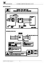
Page 25: ...DUPLOMATIC E M DDC4 400V RK RELEASE 1 9 07 09 EM DDC4 400 RK 0709gb doc 25 DRIVER SUPPLY ...
Page 27: ...DUPLOMATIC E M DDC4 400V RK RELEASE 1 9 07 09 EM DDC4 400 RK 0709gb doc 27 ...
Page 28: ...DUPLOMATIC E M DDC4 400V RK RELEASE 1 9 07 09 EM DDC4 400 RK 0709gb doc 28 ...
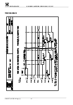
Page 30: ...DUPLOMATIC E M DDC4 400V RK RELEASE 1 9 07 09 EM DDC4 400 RK 0709gb doc 30 TIME DIAGRAM ...


