DUPLOMATIC E.M.DDC4-400V/RK RELEASE 1.9 07-09
EM DDC4-400-RK-0709gb.doc
16
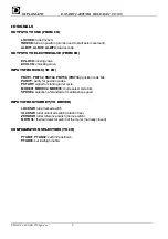
(6) In this case a slow SSI - like protocol (Serial Synchronous Interface) is enabled using the ALBITs outputs.
SIGNAL
READY CLOCK DATA
OUTPUT
ALBIT1 ALBIT2 ALBIT4
The READY signal is independent an is ON if the turret is OK.
If the turret is in alarm or in emergency, READY is OFF.
The data transmitted are: (MSB fist, LSB last) in order:
Byte 1: FULL ALARM CODE (HEX eg. Alarm 35 -> 0011 0101)
Byte 2: Turret Position (0-> turret out of position; <>0 turret is/can be locked on the position )
Byte 3: Digital inputs 1:
In
order
(
ZEROSW,ULCKSW,LOCKSW, MOTVL,PTAB03,MOD03,MOD02,MOD01
)
Byte 4: Digital inputs 2:
In
order
(
PTAB02,PTAB01,PSTART,PARITY,PBIT08,PBIT04,PBIT02,PBIT01
)
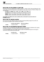
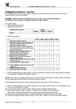
(7) The status of the switches of the turret is output as follows:
SIGNAL
MOTOVL
(thermal detector)
ZEROSW
(reference)
LOCKSW
(locking)
ULCKSW
(unlocking)
OUTPUT
INDEXD ALBIT1 ALBIT2 ALBIT4
A reset will disable this function.
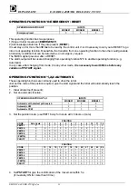
(8) Danger of collision to other parts of the lathe! Move the turret in a safe zone before starting the cycle. The
autotest function is stopped and disabled by putting the turret in emergency mode (MODE 0).
Summary of Contents for DDC4-10-400/20
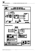
Page 24: ...DUPLOMATIC E M DDC4 400V RK RELEASE 1 9 07 09 EM DDC4 400 RK 0709gb doc 24 SERVOMOTOR CABLE ...
Page 25: ...DUPLOMATIC E M DDC4 400V RK RELEASE 1 9 07 09 EM DDC4 400 RK 0709gb doc 25 DRIVER SUPPLY ...
Page 27: ...DUPLOMATIC E M DDC4 400V RK RELEASE 1 9 07 09 EM DDC4 400 RK 0709gb doc 27 ...
Page 28: ...DUPLOMATIC E M DDC4 400V RK RELEASE 1 9 07 09 EM DDC4 400 RK 0709gb doc 28 ...
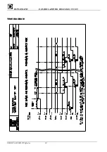
Page 30: ...DUPLOMATIC E M DDC4 400V RK RELEASE 1 9 07 09 EM DDC4 400 RK 0709gb doc 30 TIME DIAGRAM ...

