43
11.1 Beginning of Each Heating Season
• Check boiler area is free from combustible materials,
gasoline, and other
fl
ammable vapors and liquids.
• Visually inspect combustion air and vent piping for
proper operation. Check for and remove any obstruction
to
fl
ow of combustion air or vent gases. Immediately
repair or replace pipe showing deterioration or leakage.
Reassemble per instructions in section 6. Ensure proper
reassembly and resealing of system.
• Visually inspect condensate drain line for proper
operation. Checking for deteriorated or plugged
condensate drain line. Verify condensate trap drains
freely.
• Test safety relief valve for proper operation. Refer to
valve manufacturer's instructions packaged with relief
valve.
• Examine
fl
ue passages in heat exchanger, burner,
condensate lines, and cleaning (if necessary) by following
instructions in “Annual Examination and Cleaning of Boiler
Components” in this section.
• Circulator pump and combustion air blower motor
furnished with boiler are permanently lubricated from
factory and require no further lubrication. Lubricate
fi
eld
sourced pumps and/or motors according to pump and/or
motor manufacturer’s instruction.
• Check following components are operating properly and
are free of blockages or obstructions:
• air vent;
• check venturi air inlet for blockage and clean as
required;
• verify pressure test port cap and combustion test port
are in place;
• return temperature sensor clip must be securely
seated on pipe; Check boiler for any sign of leaks.
• Check low water cutoff using user interface.
• Check operation by pressing test button on low water
cutoff.
• "Low Water" LED should illuminate and burner
should shut down.
• Should get error message on User Interface
(E36).
• Every 5 years remove low water cutoff. Reinstall
after cleaning.
• Every 10 years replace low water cutoff.
• Check
fl
ame signal with user interface. Should be 8
micro
amps at 100%
fi
ring rate ( High
fi
re).
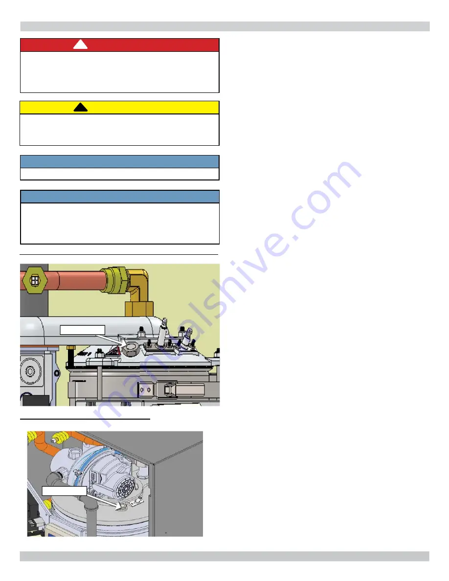
• Visual inspection of
fl
ame through sight glass. Burner
should be fully illuminated. See
fi
gures 11-1 & 11-2.
• Check heating system expansion tank.
CAUTION
Label all wires prior to disconnection when servicing
controls. Wiring errors can cause improper and
dangerous operation.
!
!
NOTICE
Verify proper operation after servicing.
NOTICE
Perform regular service and maintenance by
quali
fi
ed service agency at least once every 12
months to assure safe, trouble free operation and
maximum ef
fi
ciency.
FIGURE 11-1 Sight Glass - 050/075/100/150/200 MBH
DANGER
Before servicing, turn off electrical power to boiler
at service switch. Close manual gas valve to turn
gas supply OFF to boiler. Failure to comply will
result in death or serious injury.
!
FIGURE 11-2 Sight Glass - 299 MBH
Sight Glass
Sight Glass
11 - GENERAL MAINTENANCE AND CLEANING
Summary of Contents for DKVLT-050
Page 47: ...47 13 TROUBLE SHOOTING ...
Page 51: ...51 13 TROUBLE SHOOTING ...
Page 53: ...53 13 TROUBLE SHOOTING ...
Page 62: ...62 Supply Water Temperature Sensor Resistance Chart 13 TROUBLE SHOOTING ...
Page 64: ...64 14 WIRING DIAGRAM 14 1 Connection Diagram 050 075 100 150 200 MBH ...
Page 83: ...83 NOTES ...
Page 84: ...ECR International Inc 2201 Dwyer Avenue Utica NY 13501 web site www ecrinternational com ...


