Dungs 219 571 Instructions Manual Download Page 12

12 …16

MC • Edition 04.18 • Nr

. 219 571

E

MB- ZR... B07

MB- ZR... B07

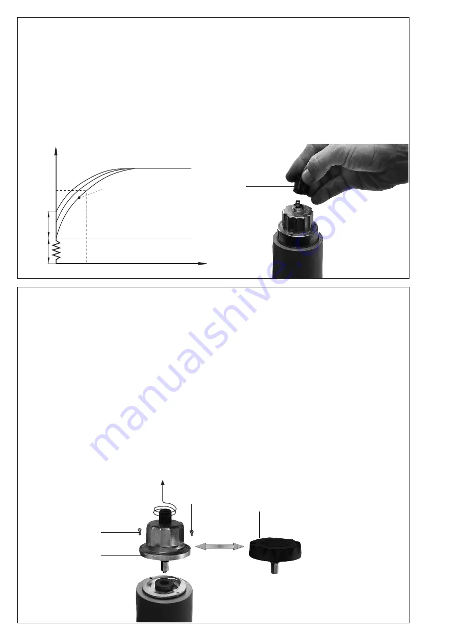
Schnellhubeinstellung V

start

Werkseinstellung  MB-ZR...B07: 

Schnellhub nicht eingestellt

1. Einstellkappe E von der Hydrau

-

lik abschrauben.

2. Einstellkappe  drehen  und  als 

Werkzeug benutzen.

3. Linksdrehen = Vergrößerung des 

Schnellhubes (+).

°

MB- ZR... B07

MB- ZR... B07

Rapid stroke adjustment V

start

Factory setting 

MB-ZR...B07: Rapid 

stroke not adjusted

1. Unscrew the adjustment cap E 

from the hydraulic brake.

2. Invert  the  adjustment  cap  and 

use as a tool.

3. Turn  anti-clockwise  =  increase 

rapid stroke (+).

°

MB- ZR... B07

MB- ZR... B07

Réglage course rapide V

start

Réglage  en  usine  MB-ZR...B07: 

Course rapide non réglée

1. Dévisser le capuchon de réglage 

E du frein hydraulique.

2. Tourner le capuchon de réglage 

et l'utiliser comme outil.

3. Rotation  à  gauche  =  augmen-

tation de la course rapide (+).

°

MB- ZR... B07

MB- ZR... B07

Regolazione scatto rapido V

start

Regolazione in fabbrica del MB-

ZR...B07:  Scatto  rapido  non 

regolato

1. Svitare dal freno idraulico il 

coperchietto E.

2. Fare  ruotare  il  coperchietto  E 

utilizzandolo come attrezzo.

3. Rotazione antioraria = aumento 

dello scatto rapido (+).

°

[m  /h

]

3

[s]

t

Werkseinstellung

Factory setting

Réglage d'usine

Regolazione in fabbrica

Schnellhub

Fast stroke

Course rapide

Scatto rapido

Zündgasmenge

Ignition gas

volume

Quantité de gaz

d'allumage

Quantità gas

d'accensione

D

B

A

C

Replacing hydraulic brake unit 

or adjustment plate

  1.  Switch off firing system.

  2.  Remove  locking  varnish  from 

countersunk screw A.

  3.  

Unscrew countersunk screw A.

  4.  

Unscrew socket head screw B.

  5.  Raise  adjustment  plate  C  or 

hydraulic brake D.

  6.  Exchange adjustment plate C 

or hydraulic brake D

  7.  Screw  in  countersunk  and 

socket head screw. Only tighten 

socket head screw so that 

hydraulic brake can just be 

turned.

  8.  Coat countersunk screw A with 

locking varnish.

 9.  Leakage test: Pressure tap 

at seal plug 4

   p

max.

 = 360 mbar.

 10.  Perform functional test.

 11.  Switch on firing system.

Austausch  Hydraulik oder 

Einstellteller

  1.  Anlage ausschalten.

  2.  Sicherungslack  über  der 

Senkkopfschraube  A  entfer

-

nen.

  3.  Senkkopfschraube  A  aus

-

schrauben.

  4.  Zylinderkopfschraube B aus

-

schrauben.

  5.  Einstellteller C bzw. Hydraulik  

D abheben.

  6.  Einstellteller C bzw. Hydraulik  

D austauschen.

  7.  Senk-  und  Zylinderkopfschraube 

wieder eindrehen. Senkkopfschrau

-

be nur so festziehen, daß Hydraulik 

noch gedreht werden kann.

  8.  Senkkopfschraube  A  mit  Si

-

cherungslack überziehen.

  9.  Dichtheitsprüfung  über 

Druckabgriff Verschluß- 

schraube  4 

 p

max.

 = 360 mbar.

10. Funktionskontrolle durchfüh-

ren.

11.  Anlage einschalten

Remplacement du frein hydrauli-

que ou du disque de réglage

  1.  Mettre  l'installation  hors  ten-

sion.

  2. 

Eliminer le vernis de blocage audes-

sus de la vis à tête fraisée A.

  3.  Dévisser la vis à tête fraisée A.

  4.  Dévisser la vis à tête cylindrique 

B.

  5.  Soulever le disque de réglage       

C ou le frein hydraulique D.

  6. 

Remplacer le disque de réglage C 

ou le frein hydraulique D.

  7.  Revisser les vis à tête fraisée et 

à tête cylindrique. Serrer la vis 

à tête fraisée.

  8.  Enduire la vis à tête fraisée A 

de vernis de blocage.

  9. Contrôle d'étanchéité par la prise 

de pression bouchon fileté 4

 p

max.

 = 360 mbar.

10.  Procéder  à  un  contrôle  de 

fonctionnement.

11.  Mettre l'installation sous ten-

sion.

Sostituzione del freno idraulico 

o del piattello di regolazione

  1.  Disinserire l'impianto

  2.  Rimuovere la lacca di sigillo sopra 

la vite a testa svasata A.

  3.  

Svitare la vite a testa svasata A.

  4. 

 Svitare la vite a testa cilindrica B.

  5.  

Sollevare il piattello C o il freno D.

  6. 

Sostituire il piattello C o il freno D.

  7.  Riavvitare la vite a testa cilin

-

drica e stringere la vite a testa 

svasata  soltanto  fino  a  che 

l'idraulico possa ancora essere 

fatto ruotare.

  8.  Sigillare con la lacca la vite a 

testa svasata A.

  9. Prova di tenuta attraverso il 

tappo a presa di pressione 4

 p

max.

 = 360 mbar.

10.  Effettuare la prova di funziona

-

mento.

11.  Reinserire l'impianto.

Summary of Contents for 219 571

Page 1: ...de conformité EU Notice d utilisation Dichiarazione di conformità EU Istruzioni di esercizio e di montaggio MB ZR DLE B07 GasMultiBloc zweistufige Betriebsweise GasMultiBloc two stage mode MultiBloc gaz à deux allures GasMultiBloc bistadio Nennweiten Nominal diameters Diamètres nominaux Diametri nominali Rp Rp 1 MB ZR DLE B07 219 571 ...

Page 2: ...16 426 à la directive UE Équipements sous pression 2014 68 Ce communiqué n est plus valable si nouseffectuonsunemodification libre de l appareil Con la presente si certifica che i prodotti citati in questa panoramica sono stati sottoposti a una prova di omologazione UE e che i requisiti di sicurezza essenziali regolamentoUEsugliapparecchi a gas 2016 426 direttiva UE sulle attrezzatture a pressione...

Page 3: ...3 16 MC Edition 04 18 Nr 219 571 ...

Page 4: ...4 16 MC Edition 04 18 Nr 219 571 ...

Page 5: ...a inserzione 100 Umgebungstemperatur Ambient temperature Température ambiante Temperatura ambiente 15 C 70 C Schutzart Degree of protection Protection Protezione IP 54 nach acc selon a norme IEC 529 DIN 40 050 Familie 1 2 3 Family 1 2 3 Familie 1 2 3 Famiglia 1 2 3 Ausgangsdruckbereich Output pressure range Pression de sortie Campo in uscita S 20 S 22 4 20 mbar 0 4 2 kPa S 50 S 52 4 50 mbar 0 4 5 ...

Page 6: ...Rp Rp 1 2 Rp 3 4 Rp 1 Rp 1 1 4 Öffnungszeit Opening time Durée d ouverture Tempo aperutra 1 s 20 s 1 s 20 s max Drehmomente Systemzubehör max torque System accessories couplemax Accessoiresdusystème max coppie Accessorio di sistema Geeignetes Werkzeug einsetzen Schrauben kreuzweise anziehen Please use proper tools Tighten screws crosswise Utiliser des outils adaptés Serrer les vis en croisant Impi...

Page 7: ...ltiBloc between the threaded flanges 3 After mounting perform leakage and functional tests Esecuzione con flangia fillettata MB ZR B07 DN 15 DN 32 Montaggio e Smontaggio 1 Allentare le viti A B C e D Figure 1 e 2 2 Estrarre il GasMultiBloc fra le flange filettate 3 Dopo il montaggio effettuare il controllo di tenuta e di funziona mento Version à brides taraudées MB ZR B07 DN 15 DN 32 Montage et dé...

Page 8: ... Remonter le capot Tarare il pressostato come in figura 2 sul valore di pressione nominale prescritto agendosullarotelladella scala graduata Prestare attenzione alle istruzioni indicate dal fa bbricante del bruciatore Il pressostato scatta con pressione in discesa regolazione sulla È Rimontare la calotta Einstellung des Gasdruckwäch ters MB ZR B07 Haube mit geeignetem Werkzeug demontieren Schraube...

Page 9: ...ig 1 Possibilicampidiregolazio ne pressione in uscita 4 20 mbar e rispettivamente 4 50 mbar Mi surazione pressione sulle prese nr 4 Plombierung Plombierungsöse 2 in der Ver schlußklappe Ø 1 5 mm Plombie rungsöse3inderKreuzlochschrau be Ø 1 5 mm NachEinstellungdesgewünschten Drucksollwertes 1 Schutzklappe 1 schließen 2 Draht durch 2 und 3 ziehen Bild 2 3 PlombeumDrahtendendrücken Drahtschlaufe kurz...

Page 10: ...aconlapressione in uscita pa del regolatore vedi diagramma Dp V per V3 2 Sigillarelaregolazioneconlacca Riavvitare il coperchietto 1 1 O Ring O ring joint torique anello torico Filter filter filtre filtro 2 MB ZR B07 Filterkontrolle Filterkontrolle mindestens einmal jährlich Filterwechsel wenn p zwischen Druckanschluß 1 und 3 10 mbar Gerät ausbauen siehe Seite 3 O Ring und Filter austau schen Filt...

Page 11: ...draulic adjustment plate 2 Turn adjustment ring Turn clockwise decrease par tial volume Turn counterclockwise in crease partial volume 3 Retighten socket head screw MB ZR B07 Regolazione della portata parziale 1 stadio possibile solo su V2 1 Allentare la vite a testa cilindrica sul piatto di regolazione 2 ruotare l anello di regolazione a destra portata parziale in diminuzione a sinistra portata p...

Page 12: ...essure tap at seal plug 4 pmax 360 mbar 10 Perform functional test 11 Switch on firing system Austausch Hydraulik oder Einstellteller 1 Anlage ausschalten 2 Sicherungslack über der Senkkopfschraube A entfer nen 3 Senkkopfschraube A aus schrauben 4 Zylinderkopfschraube B aus schrauben 5 Einstellteller C bzw Hydraulik D abheben 6 Einstellteller C bzw Hydraulik D austauschen 7 Senk und Zylinderkopfsc...

Page 13: ...agramm1 Flow Diagram1 Courbe des débits 1 Diagramma di portata 1 Kurven für Geräteauswahl MB 405 412 im eingeregelten Zustand mit Normfilter Curves for equipment selection MB 405 412 in regulated state with standard filter Courbes pour la sélection des MB 405 412 réglage effectué avec filtre aux normes Curve per la scelta del tipo di apparecchio MB 405 412 in condizioni già preregolate con filtro ...

Page 14: ...flußdiagramm 1 anwenden Mechanically open with standard filter use flow diagram 1 for MB equipment selection Mécaniquement ouvert avec filtre aux normes Pour la sélection des MultiBlocs utiliser la courbe de débits 1 Aperto meccanicamente Con filtro normale Per la scelta del tipo di appareccio MB utilizzare il diagramma di portata 1 p mbar 2 3 4 5 6 1 8 10 20 30 40 60 80 100 50 2 3 4 5 6 1 7 8 910...

Page 15: ...es surfaces de brides Serrer les vis en croisant Lors du montage il faut eviter de tirer sur les vis du MultiBloc Seuldupersonnelspécia lisépeuteffectuerdestra vaux sur GazMultiBloc WorkontheGasMultiBloc mayonlybeperformedby specialist staff Protect flange surfaces Tighten screws cross wise Make sure that the device is mounted free of strain Do not allow any direct contactbetweentheGas MultiBloc a...

Page 16: ...o di cicli di funzionamento di progetto Zeit Jahre Time years Durée année Periodo anni Ventilprüfsysteme Valve proving systems Systèmes de contrôle de vannes Sistemi di controllo valvole 250 000 10 EN 1643 Gas Gaz Druckwächter Pressure switch Manostat Pressostati 50 000 10 EN 1854 Luft Air Aria Druckwächter Pressure switch Manostat Pressostati 250 000 10 EN 1854 Gasmangelschalter Low gas pressure ...

Reviews: