5. Using On-Screen Menu
115
Adjustment method
1. Align the cursor with the [HORIZONTAL CORNER] or [VERTICAL CORNER] of the [GEOMETRIC
CORRECTION] menu and then press the ENTER button.
• The adjustment screen will be displayed.
2. Press the
▼▲◀▶
buttons to align the cursor (yellow box) with the target adjustment point
and then press the ENTER button.
• The cursor will change into an adjustment point (yellow in color).
3. Press the
▼▲◀▶
buttons to adjust the corners or sides of the screen and then press the
ENTER button.
• The adjustment point will go back to being a cursor (yellow box).
Explanation of screen transition
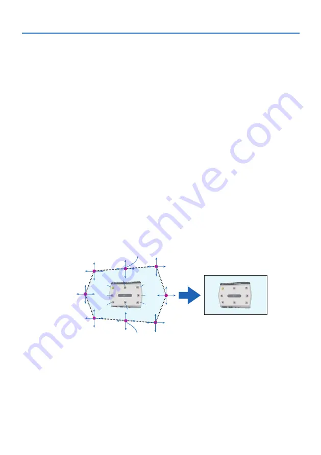
• The adjustment points of the four corners (a, c, f and h in the drawing) will move indepen-
dently.
• The following adjustment points differ at the [HORIZONTAL CORNER] and [VERTICAL COR-
NER].
HORIZONTAL CORNER: When Point b in the drawing is moved, and the upper side and Point
g are moved, the lower side will move in a parallel manner.
VERTICAL CORNER: When Point d in the drawing is moved, and the left side and Point e are
moved, the right side will move in a parallel manner.
[Adjustment points of the [HORIZONTAL CORNER] screen and movement points of the
projection screen]
a
b
b
c
d
e
f
g
h
a
c
d
e
f
g
h
Point b will be displaced in a parallel manner at the same time as Points a, b, c
Point g will be displaced in a parallel manner at the same time as Points f, g, h
Summary of Contents for 6710UL
Page 1: ...Projector 6710UL 6782UL User s Manual For USA ...
Page 239: ......


