background image

Panel indicators and switches

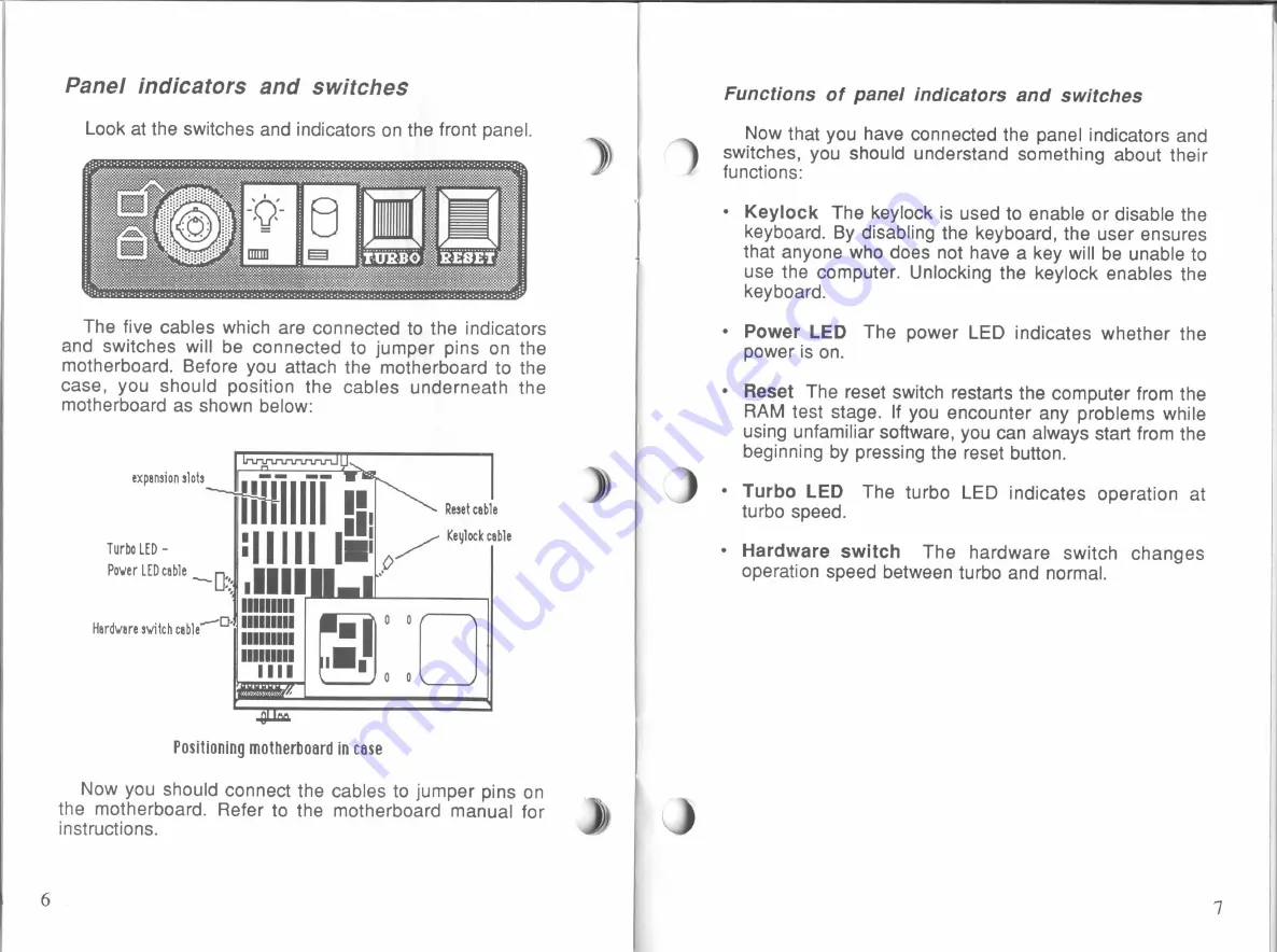
Look

at

the switches and

indicators on

the

front panel.

The

five

cables

which

are connected

to

the

indicators

and switches

will

be connected

to

jumper pins

on

the

motherboard.

Before you

attach the motherboard

to

the

case,

you

should position the

cables

underneath the

motherboard

as

shown below:

Reset cable

Ill

TurboLED _

:II

I

I

I

I

I.

/

Keulockcable

Power LEDcable

“Dz;

Illll

If?

IIIIIIIII

MD: IIIIIIIII

IIIIIIIII

IIIIIIIII

expansion slots

Hardware switch cable

Positioning motherboard

in

case

Now

you

should connect the cables

to

jumper

pins on

the motherboard. Refer

to

the motherboard manual

for

instructions.

)i

D

%

Functions of

panel

indicators

and

switches

Now

that

you

have connected the panel

indicators

and

switches,

you

should understand something about their

functions:

Keylock

The keylock

is

used

to

enable

or

disable the

keyboard.

By

disabling

the keyboard, the user

ensures

that anyone

who

does

not have

a

key

will

be

unable

to

use the computer.

Unlocking

the

keylock

enables the

keyboard.

Power

LED

The power

LED

indicates whether the

power

is

on.

Reset

The

reset

switch

restarts the computer

from

the

RAM

test stage.

If

you

encounter

any

problems

while

using unfamiliar software, you

can

always

start

from

the

beginning

by

pressing the reset

button.

Turbo

LED

The turbo

LED

indicates operation at

turbo

speed.

Hardware switch

The hardware switch

changes

operation speed between

turbo

and

normal.

All manuals and user guides at all-guides.com

Summary of Contents for Data-1000

Page 1: ...DA TA 1000 All manuals and user guides at all guides com...

Page 2: ...tem this manual and all illustrations in it are copyrighted with all rights reserved Under the copyright laws the Data 1000 Turbo system this manual and the illustrations may not be copied without the...

Page 3: ...Reorient the receiving antenna Relocate the computerwith respect to the receiver Move the computer away from the receiver Plug the computer into a different outlet so that the computer and the receive...

Page 4: ...o the computer world will find this system ideal for their first step experienced hands will also appreciate the flexibility that they are allowed in con figuring the system to their own special needs...

Page 5: ...t PC store Application software is what you use for work and play A spreadsheet program is an example of this kind of soft ware g Installation E 5 E 5 Ei 2 IE 5 f5 125 115 IS lig i 52 51 2 EI E 3 251...

Page 6: ...uration that you may require You are now ready to install the motherboard First find the cardboard box of miscella neous parts and from it select the following Take the plastic fitting and snap it in...

Page 7: ...i D Functions of panel indicators and switches Now that you have connected the panel indicators and switches you should understand something about their functions Keylock The keylock is used to enabl...

Page 8: ...onnec ons Ali connections from the system unit to external periph erals and a power source are at the back of the case As always you should be certain all power switches are turned off before connecti...

Page 9: ...d at the upper right corner of the motherboard To connect the power supply to the motherboard find the two 6 pin connectors from the power supply and plug them into the connector on the motherboard Th...

Page 10: ...only rated 6A 125V 16ft in length 12 l Drive installation 3 The number of floppy disk drives to be installed is usually optional Up to two floppy disk drives and two hard disks may be installed in th...

Page 11: ...des of the disk drive s as shown below Screws Screws Note that the plate on the right side as you see in the picture is slightly smaller Follow the same procedure to connect the second disk drive 14 F...

Page 12: ...mistake The two hard disk controller cables are of different sizes the red wires on the cables should be connected toward the central portion of the case Next connect the metal plate as shown in the...

Page 13: ...yboard into the keyboard connector at the back Keyboard connector The rest of this section will explain the usage of the keyboard 18 Specifications 3 Case specrflcatrons External view of case Ks LI U...

Page 14: ...lock cable The panel has all the features shown above a keylock a power LED a reset switch and a turbo switch The cables from the panel connect to the motherboard as shown in the motherboard manual Al...

Page 15: ...All manuals and user guides at all guides com...

Reviews: