5
Servers located behind NAT, you need to open UDP6055 on the NAT router both at the remote site and on
your site. ( With our NAT Proxy Server, you don’t need to modify any setting on the NAT device. )
Gateway Configuration
The Blaze System supports analog and digital gateway. The followings will guide you through the
installation of analog gateways. For digital gateways, please refer to the Blaze administrator operation
guide.
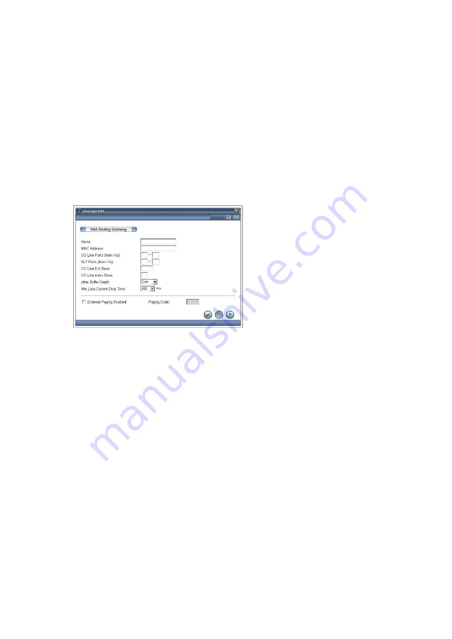
Add Analog Gateway
1.
Go to Main Menu>Gateway Configuration>Analog Gateways.
2.
Click on Add button to set your Analog Gateway List.
3.
Enter the name and the MAC address of Voice Gateway.
4.
Enter the range of CO Line Port and SLT ports from 1 to 24 respectively based on how many FXO and
FXS ports on the gateway.
5.
At “CO Line Extension Base” input the starting number of CO Line extension number. The CO Line
extension numbers will be assigned automatically. For example if you set it as 4000 for an 8-port FXO
gateway, the CO Line extension number of this gateway will be 4000-4007.
6.
At “CO Line Index Base” input the starting number of the CO line displayed number. For example if
you set it as 1, when there is an incoming call from port 1, the IP phones will display “Incoming Call
CO 1” instead of the extension number of the port, helping you to identify the CO lines being used
7.
From “Jitter Buffer Depth” drop down menu, depending on your bandwidth and CODEC, start with a
Jitter Buffer with the minimum value. Jitter Buffer will dynamically adjust its value according to the
party you are talking to and the bandwidth of the call but never below the value you have set. The
higher value of Jitter Buffer will reduce the chance of packet loss during a call but might cause delays
and the lower value will help to transmit the voice packets faster but might cause packet loss
problems.
Summary of Contents for Blaze 1200 Series
Page 20: ...20 10IPBXQ BZ2 32b EN3...


