22
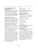
2. Using a short jumper, short pins marked “EEPROM
RESET” together.
3. Power PC3000 up.
4. Wait for 10 seconds. During this time the “Program” light
will flash.
5. Remove the shorting jumper.
6. The system will have reloaded the EEPROM with the
factory default codes.
[35] Through [42] - For Future Use
[43] Access Bypass Mask (Codes 1 to
8)
Use the same method of programming as used in section
[18]. In this section it is possible to control which users can
bypass zones. If the zone light is on, that user can bypass, if
that zone light is off, that user cannot bypass.
[44] Access Bypass Mask (Codes 9 to
16)
Program using the same method as section [43].
Note: Zone lights 1 to 8 represent access codes 9 to
16.
[45] TLM Restoral Reporting Code
Once the code is programmed, the panel will transmit the
reporting code every time that a phone line trouble is
restored. This will also initiate transmission of all codes
unsuccessfully transmitted during the phone line fault.
[46] Downloading Computer Telephone
Number
This is the telephone number that the panel would use to call
the downloading computer if the CALLBACK feature
(section [47]) is enabled or if a user initiated call up is done.
([
Q
]+[6]+[ Master Code]+[ 9]).
[47] Modem Configuration
This section is used to enable the Downloading function. If
Downloading is enabled then the Downloading access code
must be entered, (section [26]) and the Panel Identification
Code must be entered. (section [48]). If Callback is enabled
the downloading computer's telephone number must be
entered. (section [46]).
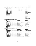
[1] to [4] See chart on page 36
[5] Light off= Downloading disabled
Light on= Downloading enabled
[6] Light off= No user initiated call up
Light on= User initiated call up
[7] Light off= Answering machine over-ride disabled
Light on= Answering machine over-ride enabled
[8] Light off= Call back disabled
Light on= Call back enabled
(See “Downloading”)
[48] Panel Identification Code
Program using the same method as sections [24], [25] and
[26].
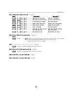
[49] Printer Configuration
[1] Light off= Not 110 baud
Light on= 110 baud selected
[2] Light off= Not 300 baud
Light on= 300 baud selected
[3] Light off= Not 1200 baud
Light on= 1200 baud selected
[4] Light off= Not 2400 baud
Light on= 2400 baud selected
[5] Light off= Printer and normal communications
Light on= Printer only
[6] Light off= Printer and normal communications
Light on= See Note (1)
[7] Light off= Printer Yellow to PIN 11, SRTS
Light on= Printer Yellow to PIN 4, RTS or to PIN 20, DTR
[8] Light off= Test transmission enabled
Light on= Periodic downloading enabled
Note (1):
IF ZONE LIGHT 6 IS ON AND ZONE LIGHT 5 IS OFF: All
items whose reporting codes are programmed for
telephone #1 will be communicated to the monitoring
station AND printed on the printer. All items whose
reporting codes are programmed for telephone #2 will
NOT be communicated to the monitoring station but
will be printed on the printer.
IF ZONE LIGHT 5 AND 6 ARE OFF: All items whose
reporting codes are programmed for telephone #1 or
telephone #2 will be printed on the printer and
communicated to the monitoring station.
IF ZONE LIGHT 5 IS ON: All items whose reporting
codes are programmed for telephone #1 or telephone #2
will be printed on the printer but will not be
communicated to the monitoring station. In this case it
is assumed that telephone lines are not connected. DO
NOT disable the communicator. The 1st System Option
Code, zone light [1] must be OFF. To avoid TLM
trouble, program 2nd System Option Code light [7] to
be ON.
[50] After Alarm Reporting Code
Program using the same method as sections [05] to [15].
This code will be transmitted with or instead of an opening
code if an alarm occurred during the last armed state. '00' or
'FF' in this section will disable the feature.
[51] 3rd System Option Code
[1] Light off= Bell squawks once every 10 seconds during
auto-arm
Summary of Contents for PC3OOO
Page 1: ...INSTALLATION MANUAL PC3OOO Version 7 51...
Page 40: ...HOOKUP DIAGRAMS 36...
Page 44: ...29000543 R7...


