background image


Page | 60  


Dryer Master DM510  


Installation Manual


Connecting to a Drying Air Temperature Sensor 


GND

+24VDC

Temp

GND

Rate Out

Output 2

Gnd.

Rate In

GND

S

p

e

e

d


S

e

n

s

e

Rate In

S

p

e

e

d


C

o

n

tr

o

l

A

ir

 T

e

m

p

Rate Out

G

N

D

Output 2

+24VDC

TEMP

GND

G

N

D

Drying Air Temperature

4

RED

BLACK

WHITE

GROUND

SHIELD

GROUND

Drying Air

Temperature

Sensor

4

RED

BLACK

WHITE

To pigtail in vertical 

wire tray

Solid State Temperature probe 

Signal specification

Red 

= 18 to 30 vdc, 2mA 

Black =  Gnd.

White = Temperature signal

Dryer Master DM510


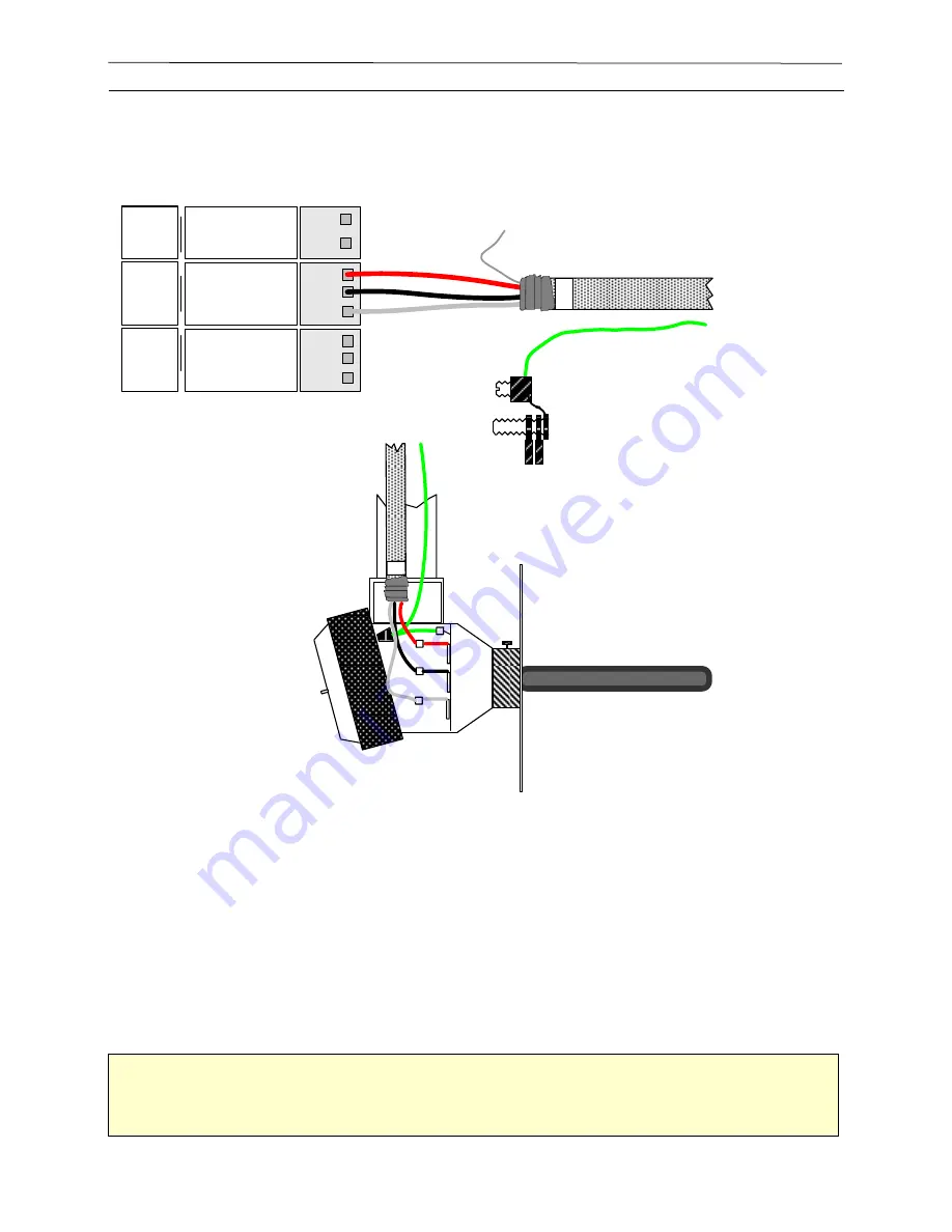
This device measures the temperature of the drying air in the air plenum. If the temperature 
controller for the dryer does not have a scaled output use the Drying Air Temperature Sensor 
supplied with the DM510.  For both options remember to attach the Multi-cable shield to ground at 
Dryer Master end and insulate it on the other end.  


Mount the Drying Air Temperature Sensor within one foot of the existing temperature sensor in the 
hot zone of the dryer.  Both sensors should be at the same height.  Use high temperature wire from 
the Drying Air Temperature Sensor to the outside of the hot zone.  At this point the standard two 
pair shielded cable can be used.  

Hint 

Caulk the conduit entry into the hot zone of the dryer with silicone. This avoids a hot draft 

heating up the conduit near your splice. 


Figure 43 - Drying Air Temperature Sensor Wiring 

Summary of Contents for DM510

Page 1: ...INSTALLATION GUIDE ...

Page 2: ...r Ontario Phone 519 725 4700 Fax 519 885 4300 USA and Canada Toll free at 1 888 318 0009 E mail info dryermaster com Reminder Remember to register your DM510 at dryermaster com Simply by registering your new DM510 you automatically extend your warranty from 1 year to 2 years February 28 2015 January 15 2016 January 31 2017 March 30 2018 ...

Page 3: ...ral examples shown in this guide but each situation can be somewhat unique so if you have questions ask us before beginning the installation Once you have completed the installation the next step will be to use the Commissioning Guide to tailor the DM510 to your particular dryer Do not attempt to use the DM510 to control your dryer before completing the commissioning process If you have questions ...

Page 4: ...or 11 Configuration with Remote I O and APT sensor 12 Configuration with Integrated I O and Temperature Signal Converter 13 Project Manager Guide and Checklist 14 Installation Overview 14 Situation 1 Overview Installation on new dryer when purchased from dryer manufacturer 14 Situation 2 Overview Retrofit onto an existing dryer 15 Installation Checklist 16 DM510 Control Panel 16 Dryer Master I O s...

Page 5: ...1a Bypass Using Sampling Auger 31 Option 2 In Line Method Details 33 DM510 Control Panel Installation 35 Control Panel Location 35 Control Panel Installation 35 I O Panel Installation 37 Power and Grounding Requirements 39 DM510 Control Panel 39 Moisture Sensors 44 AC Motor Speed Control Interface 44 DC Motor Speed Control Interface 44 Control Wiring Requirements 45 Motor Controller and Ground Wir...

Page 6: ...T SENSOR INSTALLATION ON A GRAIN HANDLER DRYER 23 FIGURE 6 SENSOR AND MOUNTING PLATE DIMENSIONS 25 FIGURE 7 ALTERNATE LOCATION FOR INLET SENSOR ON COLUMN DRYER 26 FIGURE 8 ROUND DRYER INSTALLATION LOCATION 26 FIGURE 9 OUTLET FIN IN CHUTE PHOTO 28 FIGURE 10 BY PASS WITH ROTARY METERING 29 FIGURE 11 EXAMPLE INSTALLATIONS OF BY PASS WITH ROTARY METERING 30 FIGURE 12 BY PASS AUGER INSTALLATION 32 FIGU...

Page 7: ...GNAL CONVERTER 59 FIGURE 42 AIR PLENUM TEMPERATURE SENSOR 59 FIGURE 43 DRYING AIR TEMPERATURE SENSOR WIRING 60 FIGURE 44 APT CONTROLLER ANALOG CONNECTION 61 FIGURE 45 DM510 TO SIGNAL CONVERTER WIRING 62 FIGURE 46 CALIBRATION PUSH BUTTON 63 FIGURE 47 REMOTE ALARM 64 FIGURE 48 DM510 TO MITSUBISHI FR D700 65 FIGURE 49 DM510 TO GENERIC VFD O 10 VDC 66 FIGURE 50 DM510 TO ALLEN BRADLEY POWERFLEX40 66 FI...

Page 8: ...andard platforms that are extremely flexible and readily configured by the end user In support of our real time advanced control systems DMSI provides a full range of hardware and software engineering services system commissioning operator training and over the phone remote support We deliver proven solutions resulting in increased yields improved and consistent product quality maximized plant eff...

Page 9: ...that grain drying is a very difficult process to control You know that your dryer dries faster or slower depending upon drying conditions Ambient air temperature wind speed and direction humidity time of day the variety of the grain being dried and of course the moisture of the grain all can affect dryer operation The Dryer Master DM510 uses sophisticated on line moisture measurement and moisture ...

Page 10: ...verages hourly and daily reports and bin summaries These are tools that can be used to manage the total drying process Inlet Moisture and Temperature Sensor The inlet moisture and temperature sensor is installed in the flow of the product before it enters the drying zone hot zone of the dryer typically in the garner or holding bin above the hot zone Outlet Moisture and Temperature Sensor Chute wit...

Page 11: ...e Sensor Outlet Moisture Temperature Sensor Moisture Sample Start Button Dryer Control Panel Discharge Speed DRYER DM510 Control Panel 5 6 7 2 3 1 4 Instrumentation cables Ground cables Internet connected router or wireless access point WAP 8 1 Inlet Sensor 2 Outlet Sensor 3 Push Button 4 Drying Air Temperature Sensor 5 Rate Sense and Rate Control 6 Local Remote Control andLocal Remote Status 7 Fa...

Page 12: ... I O Box cables Instrumentation Internet Router or Wireless Access Point WAP 10 11 Communicatons and Power Cable Spare 1 5 3 2 6 8 7 1 Inlet Sensor 2 Outlet Sensor 3 Push Button 4 Drying Air Temperature Sensor 5 Rate Sense and Rate Control 6 Local Remote Control andLocal Remote Status 7 Fan Status 8 Spare 9 Remote Alarm Optional 10 Communications and Power Wire 11 Spare Communications and Power Wi...

Page 13: ...ure Temperature Sensor Moisture Sample Start Button Dryer Control Panel Discharge Speed DRYER DM510 Control Panel 5 6 7 2 3 1 4 Instrumentation cables Ground cables Internet connected router or wireless access point WAP 8 1 Inlet Sensor 2 Outlet Sensor 3 Push Button 4 Plenum Temperature Signal Converter 5 Rate Sense and Rate Control 6 Local Remote Control andLocal Remote Status 7 Fan Status 8 Spar...

Page 14: ... a purchase order To provide over the phone assistance during the installation process and during system start up To assist the site operator s by phone during the drying season Dryer Supplier System Installer Responsibilities To mount the inlet moisture sensor the outlet moisture sensor the drying air temperature sensor or temperature signal converter the sample button and the Dryer Master I O sy...

Page 15: ...let moisture sensor the drying air temperature sensor or temperature signal converter the sample button and Dryer Master I O system if not retained in the DM510 cabinet To mount the DM510 panel To install conduit and run wiring from the DM510 panel to the Dryer Master I O system If applicable To install conduit and run wiring from the field devices to the Dryer Master I O system To terminate conne...

Page 16: ...nt will afford extra surge and lightning protection Surge protection and or a UPS if power is unstable may be of benefit The DM510 control panel is to be located in the control room from where the operators currently control operations For viewing ease it is recommended that the DM510 control panel be mounted so that the bottom of its display screen is at or slightly above average eye level Meets ...

Page 17: ...sed specifications for the chute dimensions and product conveyance methods are provided in separate mechanical drawings Communication with DMSI Engineering personnel could result in revisions to the installation method if the flow rate is not within specification DMSI Project Engineering can advise you of modifications to the required installation Installed the sensor chute as specified Installed ...

Page 18: ...nstallations of the DM510 on older dryers with DC drives require the use of the DM510 motor speed control interface The interface provides isolation and signal conditioning between the DM510 and the speed control The interface is located in the dryer control panel near the motor speed limit Installed the motor speed control interface as specified Connected the motor speed control interface as spec...

Page 19: ...panel to the field instrumentation for the integrated I O solution Three 3 16 AWG minimum ground wires should be pulled from the DM510 chassis ground to specific field instrumentation and Dryer s Control panel For the remote I O two instrument cables one as a spare need to be pulled between the remote I O panel and the DM510 panel plus a 16 AWG minimum ground wire It is recommended that the ground...

Page 20: ...m the Dryer electrical panel to DM510 panel G4 from the remote I O panel to DM510 panel if configured this way The conduit must enter the DM510 control panel through the supplied entry plug on the bottom right or bottom of the cabinet Any other entry may damage equipment and void warranty Flexible liquid tight conduit is to be used at the moisture sensors so that they can be easily removed for ser...

Page 21: ...ide Commissioning Guide Laminated Quick Guide Instrumentation wire 1000 Sensor chute bypass or inline version Support Telephone assistance for installation and setup and system support The support staff can be reached at 1 888 318 0009 Customer supplied components and services Hardware Connection to an internet enabled router or WAP wireless access point for DM Mobile functionality Site Mill work ...

Page 22: ...nterchangeably In some unique situations a Round Cell sensor design may be used in place of the fin sensor either at the inlet or the outlet Note It is important that you read all of the directions before proceeding with the installation The correct operation of the sensor and the Dryer Master depends on the correct installation of the moisture sensors Caution Welding on or welding near the sensor...

Page 23: ...yer Installation should minimize the probability of steam reaching the sensor Install the Inlet Sensor at a level higher above the hot zone than the width of the hot zone For example if the hot zone is a foot wide leave at least a foot between the hot zone and the sensor If this is not done the static pressure in the hot zone can force moisture laden air past the sensor Due to the cold state of th...

Page 24: ...ide wall of the garner bin to cover the hole such that the sensor can be mounted through the plate without binding 4 Bolt the Sensor to the mounting frame Make sure that the sensor is mounted such that the wire entry will be down If you are unsure of where to locate the sensor contact the Dryer Master Support Center It is preferable to do it right the first time Note Locate the sensor where it is ...

Page 25: ...Page 25 Dryer Master DM510 Installation Manual Inlet Sensor Dimensions 8 1 2 6 Mounting Plate Inlet Sensor 10 11 Mounting Frame Dimensions Figure 6 Sensor and mounting plate dimensions ...

Page 26: ...Page 26 Dryer Master DM510 Installation Manual Additional Sensor Location Diagrams Figure 7 Alternate location for inlet sensor on column dryer Figure 8 Round dryer installation location ...

Page 27: ... Any outlet sensor installation needs to fulfill a number of requirements as outlined below 1 The chute needs to hold a compacted yet flowing sample of grain minimum possible airspace between kernels 2 Sample size needs to be large enough to have statistical relevance 3 Sensor needs to be mounted in a vertical position to minimize the influence of fines on the moisture reading 4 Operator must be a...

Page 28: ...ic meters per hour Install the chute so that there will be a continuous flow of grain and the chute will remain full Ensure that the grain flowing through the chute is a good representative sample of the grain to be tested Place the sensor in a location where it will NOT get an excess of fines or trash as this will Figure 9 Outlet Fin in chute photo Warning Welding on or near the sensor while it i...

Page 29: ... to the sensor to allow cleaning out and or servicing the sensor 4 Install bars across the opening to the sensor in the direction of grain flow This will prevent large objects from entering the sensor 5 Mount the chute in a vertical position 6 Bolt the fin sensor back into the chute Do not cut holes in the Outlet Sensor Use only the existing wire entry location Entry at any other location voids th...

Page 30: ...ryer Master DM510 Installation Manual See also Appendix 3 for additional information on the Dryer Master bypass chute with rotary feed installation Figure 11 Example installations of By Pass with rotary metering ...

Page 31: ...able 1 Gear reductions for metering devices All gear reductions given are based on a chute that is six inches by six inches For the best flow characteristics it is recommended that the auger be opened to the full width of the chute This will also reduce transition complexity Verify the auger flow and gear box required The table is an approximate guideline Installation Procedure 1 Remove the Outlet...

Page 32: ... and ensure the grain flows evenly past the fin Also ensure that the auger is drawing grain from all areas of the chute Figure 12 By Pass auger installation Figure 13 By Pass auger installation Dry Grain Leg Dry Grain Drag Bypass Chute Viewing Window Sample Return Auger Moisture sensor ...

Page 33: ... the dry grain auger or drag Install the Chute and Sensor in a continuous flow of grain and where the sensor will remain full Install the Chute and Sensor so the operator can inspect and clean the sensor It must be possible to do these tasks easily and safely while the dryer is operating Installation Procedure Note for the Dryer Master In Line chute with rotary feed additional photos are in Append...

Page 34: ...wire entry location Entry at any other location voids the warranty Calibration Push Button Bypass Fin in Chute Resrtictor Slide Gate Dry grain Drag Discharge Hopper of Zimmerman Dryer Zimmerman Chute Figure 16 Dryer Master rotary feed chute inline version Figure 17 Example of GSI Zimmerman chute Installation ...

Page 35: ...r the alarm buzzer The bottom of the display screen LCD is slightly above average eye level Locate DM510 in a room where the dryer operators will spend most of their time or will be processing moisture samples If the DM510 is mounted against an uninsulated outside wall provide 12 7mm insulating panel wood Control Panel Installation Refer to Figure 21 DM510 Control Panel Dimensions while doing the ...

Page 36: ...0 Control Panel Cuttings getting inside the panel can cause serious damage Use only existing wire entry locations The warranty is void if additional holes are made in the DM510 Control Panel 15 14 12 0 5 0 38 typ 0 5 Eye Level 1 Flange Top and bottom Figure 18 DM510 Product Dimensions ...

Page 37: ...m the weather in a NEMA 4 box or in the dryer control panel The ambient temperature during operation will be between 40 and 105 F 5 and 40 C The I O panel is away from high potential voltage and all unprotected Multi cables coming in from remote sensors are not near high power cable areas Or it is physically protected with metal shielding Wiring is done in accordance with local electrical codes an...

Page 38: ...s Cut two Multi cables that are long enough to reach between the DM510 and the location of the I O panel One will replace the current cable and the second will be a spare Mark them to identify them from each other Pull these cables along with a 16 awg Green ground wire into the conduit between the DM510 and the I O panel Rewire the end connectors as noted below and connect them to the noted locati...

Page 39: ...l panel will assure the equipment is grounded even if it is unplugged Damage caused by electrical surges and lightning are not warranted System Grounding Configuration A typical electrical installation includes a number of electrical devices or equipment each with its own ground connection The relationship between these ground connections will affect the overall performance of the system especiall...

Page 40: ...h ground system This is illustrated in Figure 21 Star Point Grounding For simplicity only the ground wiring is shown and not other wiring that normally interconnects the devices Drying Air Temperature Sensor Inlet Moisture Temperature Sensor Outlet Moisture Temperature Sensor Moisture Sample Start Button DM510 Control Panel Dryer Control Panel Discharge Speed Ground Rod Figure 21 Star Point Ground...

Page 41: ... star but will be small in magnitude in a well designed system A larger voltage will be seen on the conductor between the star connection and the earth ground connection but will have little consequence on the connected equipment as each device will see an equal rise in ground potential This limits current conduction through sensitive equipment due to differences in ground potential Figure 22 Effe...

Page 42: ...es that current flow in the ground wiring results in increasing differences in ground potential in each piece of equipment connected downstream from the surge event The result can be current flow between devices as a result of a difference in ground potential Equipment Equipment Equipment Equipment Equipment i V i Z1 Z2 Z3 Z4 Surge Current i Z1 Z2 Z3 Z4 Z5 i i Figure 23 Effects of surge current in...

Page 43: ...nd Temp Outlet 2 24V COM T3 M3 __ Com DO 2 NO NC COM Outlet 1 Calibrate Lamp Output Rate In B A B A B A B A Note Pre 2015 I O Jumpers must be installed connecting GND to the B terminals of the used digital inputs and the Com terminals of the used digital outputs All the Com and B terminals are shown connected to GND in this drawing Moisture 24 Gnd Temp Outlet 1 24V COM T2 M2 __ Moisture 24 Gnd Tem...

Page 44: ...ntrol A 24V relay is required to switch between the local control signal and the DM510 speed input DC Motor Speed Control Interface Discharge Rate Monitoring The Motor Speed Control Interface converts the 0 to 90 180 VDC output from the motor speed control to an isolated 0 to 5 V signal for the DM510 Discharge Rate Sense input Discharge Rate Control The Motor Speed Control Interface converts the 0...

Page 45: ...anel See below for details Two pair shielded minimum 22 AWG 644 mm or 23 SWG stranded tinned copper conductors and drain wire e g Beldon 8723 PVC jacket rated for 140 F 60 C The Dryer Master supplied wire is rated to 105 C Colour code black red green white recommended In areas where the temperature will exceed 140 F use a wire with a higher jacket rating e g Beldon 88723 Figure 25 Multi Cable Diag...

Page 46: ... Cable Remote Calibration Button DM510 Control Panel 4 2 Multi Cables Drying Air Temperature Sensor DM510 Control Panel 5 and 6 2 Multi Cables 1 ground Motor Speed Control Interface and Local Remote Status DM510 Control Panel 7 1 Multi Cable Fan Status optional DM510 Control Panel 8 1 Multi Cable Spare DM510 Control Panel 9 1 Multi Cable Remote alarm optional DM510 Control Panel 10 and 11 2 Multi ...

Page 47: ...ons during installation and service Install the conduit into the DM510 Control Panel through the supplied entry plug See Figure 27 Wire Entry Locations Remember that it is easy to damage Multi Cable when pulling into a conduit Careful installation when doing this will save time and money When cutting Multi Cable and placing it in the conduit allow An extra 24 75 cm at the DM510 Control Panel end A...

Page 48: ...able is so equipped Use the needle nose pliers to pull ripcord so the desired length of wire is exposed Cut off the original of the cable as it may have been nicked when the PVC jacket was removed and could cause problems at a later date 3 Remove the insulation using cable strippers The use of a knife is not recommended because of the risk of damaging the insulation of the conductors 4 Use the sid...

Page 49: ...4 Gnd Inlet 24V COM T1 M1 __ Com Outlet 1 Calibrate Lamp Output Com Outlet 2 Calibrate Lamp Output Com Remote Alarm Output Temp Temp Inlet Moisture 1 Drying Air Temperature 4 Outlet Moisture 2 Calibration Button 3 Rate Sense Control 5 Local Remote Status 6 Fan Status 7 Spare 8 Shield drain wires twist and wire nut to drain wire provided in vertical cable tray Signal Ground Sensor Ground wires Gree...

Page 50: ... the crimp connectors provided in the sensor 5 Join the ground wire in the moisture sensor to the ground wire from the DM510 Control Panel using a wire nut The DM510 Control Panel End 1 The Multi Cables from the Moisture Sensors connect to the DM510 Control Panel termination Attach them using the connectors as indicated in Figure 29 Sensor hook up physical 2 Connect the Multi Cable drain wire and ...

Page 51: ...et Sensor Moisture 24 V Gnd Temp Black Red Green Green Red Black White Green Red Black White 1 2 1 White 2 Shield To pigtail in vertical wire tray Figure 29 Sensor hook up physical Dryer Master Control Panel Moisture Sensor Electrical Tape insulate shield from ground Wire Nut ground cable to ground wire in Sensor Ground GREEN RED BLACK WHITE Moisture 24 VDC Ground Temperature Conduit Flex conduit ...

Page 52: ...ntact closes on activation Optionally N C Normally Closed configuration Contact opens on activation Contact outputs 24 VDC or is dry contact Shown in default position Contact closes and 24 volts is present at Output Contact output dry contact or tied to GND Shown in default position tied to GND Figure 32 I O board Digital Out jumper configuration description Digital Input Configuration Jumpers Sho...

Page 53: ...ation Manual Analog Input Configuration Jumpers Shown in default 10V position for the first 7 channels Channel 8 the temperature channel is in the 5V position by default Figure 34 I O board Analog Input jumper configuration description ...

Page 54: ... with ALL options Connections from DM510 to Motor Speed Control Interface Function From DM510 To Motor Speed Control Interface Local Remote Relay DM510 Local Remote Output MSC Interface Local Remote T3 Local Remote Relay DM510 Outlet 2 GND MSC Interface Local Remote T4 Rate Sense DM510 Speed Sense Rate In MSC Interface Rate Sense T1 Rate Sense DM510 Speed Sense GND MSC Interface Rate Sense T2 Rate...

Page 55: ... T6 T7 T8 T9 T10 T11 T12 T13 T14 P 2 P 1 Rate Sense OUT GND LOC REM Control Rate Control IN GND Shield To pigtail in vertical wire tray Shield Figure 36 DM510 to MSC Interface Connections from Motor Speed Control Interface to Motor Speed Control Function From DMSI Motor Speed Control Interface To Motor Speed Control Rate Sense Input If DC Motor is 180 VDC MSC Interface ARM 180 VDC T14 DC Motor Spe...

Page 56: ...ontrol Panel Local Remote Status Wiring Instructions The Motor Speed Control Interface provides a local remote switching facility that can disconnect the manual speed dial on the dryer and allow the DM510 to control the discharge rate It is necessary for the DM510 to understand the status of this functionality This is achieved by wiring up the spare dry contact from the local remote relay used to ...

Page 57: ... Outlet 1 Calibrate Input Input Output Input Output Green 5 L R Status NO 1 NC 6 6 13 A1 Coil Black Local Remote Relay Finder 55 32 Carlo Gavazzi RMIA2 10024DC Dryer Master DM510 GND Red SHIELD 9 L R Com A2 Coil 14 To VFD 12 NC Rate From Dryer 4 NO Rate Out 8 Input COM Input COM Input COM Input COM To pigtail in vertical wire tray Red Green Black This is an optional feature If it is used the softw...

Page 58: ... Com Com Rate Out Output 2 GND Com Com Com Com 24V GND T3 M3 __ RATE IN GND Speed Sense Rate In Speed Control Air Temp Rate Out GND Output 2 24VDC Temp GND Input NO NC COM NO NC COM Outlet 1 Calibrate Lamp Local Remote Inlet 2 Calibrate Fan Status Local Remote Status Outlet 1 Calibrate Input Input Output Input Output Green 5 NO 1 NC 6 6 13 A1 Coil Customer supplied Dryer Running Relay Dryer Master...

Page 59: ...10 system 1 A Dryer Master Air Plenum Temperature Sensor to be located in the dryer 2 A signal converter that utilizes the dryer temperature information 3 Using a signal from a temperature controller with a digital or analog output Caution All multi cable must be run in areas where the maximum temperature does not exceed 105 C 220 F Use Teflon coated wires in areas that exceed this limit Figure 42...

Page 60: ...enum If the temperature controller for the dryer does not have a scaled output use the Drying Air Temperature Sensor supplied with the DM510 For both options remember to attach the Multi cable shield to ground at Dryer Master end and insulate it on the other end Mount the Drying Air Temperature Sensor within one foot of the existing temperature sensor in the hot zone of the dryer Both sensors shou...

Page 61: ...ck the temperature controller manual for the correct termination Connecting to a Temperature Controller with an analog output GND 24VDC Temp GND Rate Out Output 2 Gnd Rate In GND Speed Sense Rate In Speed Control Air Temp Rate Out GND Output 2 24VDC TEMP GND GND GREEN WHITE SHIELD Dryer Master DM510 Drying Air Temperature 4 Drying Air Temperature 4 To pigtail in vertical wire tray 185 5 Consult de...

Page 62: ...This device requires 24VDC supply DO NOT connect to 120VAC supply Damage caused by incorrect supply voltage is not covered under warranty Red DM 510 Dryer Master to Omega TXDIN70 24V converter 1 2 3 4 5 6 7 8 13 14 15 16 9 10 11 12 Existing J type Thermocouple White Channel 1 Output Channel 2 Output Channel 1 Input Channel 2 Input 24VDC Temp GND Input Com Moisture 24VDC GND Temp Moisture 24VDC GND...

Page 63: ...tput COM Outlet 1 Calibrate Lamp Local Remote X2 X1 NO NO Calibration Button 3 Calibration Button 3 White Green Red Black Calibration Button SHIELD To pigtail in vertical wire tray Button Lamp and Signal specification Red 18 to 30 VDC 40mA When Active Black GND Green N O contact 18 to 30 VDC 2 mA When Active White N O contact 18 to 30 VDC Figure 46 Calibration Push Button Mount the button where th...

Page 64: ...let 1 Calibrate Lamp Local Remote SHIELD To pigtail in vertical wire tray Output Com Output COM Output Com Output COM Outlet 2 Calibrate Lamp Remote Alarm 5 NO 1 NC 13 A1 Coil Alarm Relay Finder 55 32 Carlo Gavazzi RMIA2 10024DC 9 Com A2 Coil 14 Com 12 NC 4 NO 8 Red Black Power Source For remote alarm device Figure 47 Remote Alarm DM510 Control Panel supplies a set of relay contacts to be used if ...

Page 65: ...Calibrate Lamp Output Com DO 4 NO NC COM Remote Alarm Output Temp A1 A2 9 1 5 12 4 8 Green White Black Red Red Black 2 5 4 Existing Speed Potentiometer White Mitsubishi FR D700 series inverter Terminals White AM 10 X coil coil 3 2 1 The default reference voltage for the speed setting potentiometer is 5 Volts at terminal 10 Therefore the input signal at terminal 2 is also configured for 0 to 5 volt...

Page 66: ...utlet 2 Calibrate Fan Status Local Remote Status Outlet 1 Calibrate Input Input Output Input GND Moisture 24 Gnd Temp Outlet 2 24V COM T3 M3 __ Moisture 24 Gnd Outlet 1 24V COM T2 M2 __ Com DO 2 NO NC COM Outlet 1 Calibrate Lamp Output Com DO 3 NO NC COM Outlet 2 Calibrate Lamp Output Com DO 4 NO NC COM Remote Alarm Output Temp A1 A2 9 1 5 12 4 8 Green White Black Red Red Black 13 16 12 Existing S...

Page 67: ...iring from dryer control panel removed from terminal 2 of Baldor drive DM510 to Baldor Series H2 Variable Frequency Drive Wiring Schematic Red Black Rate Out GND 24VDC Temp GND Com Com Rate Out Output 2 Gnd Com Com Com RATE IN GND Speed Sense Rate In Speed Control Air Temp GND AO 2 R1 APT R3 R2 GND Input DI 1 DI 2 DI 3 DI 4 120V MAX A A A A B B B B 120V MAX 120V MAX 120V MAX DO 1 NO NC COM Local R...

Page 68: ...r 4 Various hand tools and wire as indicated Procedure 1 Mount the signal converter onto a DIN rail in the dryer panel 2 If desired mount the programming display to the DIN rail beside the converter 3 Use the supplied USB cable to connect the display to the converter 4 Use instrumentation cable to connect the converter signal output terminal 5 terminal 6 and power wires terminal 1 terminal 2 to th...

Page 69: ...rrect supply voltage is not covered under warranty Red DM 510 Dryer Master to Omega TXDIN70 24V converter 1 2 3 4 5 6 7 8 13 14 15 16 9 10 11 12 Existing J type Thermocouple White Channel 1 Output Channel 2 Output Channel 1 Input Channel 2 Input 24VDC Temp GND Input Com Moisture 24VDC GND Temp Moisture 24VDC GND Temp Rate In GND Rate Out Output 2 24VDC GND Temp GND Input COM Note 2 If the 250Ω pre...

Page 70: ...1 C 70 F 1 Press and hold the return key until the first parameter is displayed 2 Set input channel 1 InP1 to 3 for a T type thermocouple or 5 for a J type thermocouple using the up and down arrows 3 Press the return key to advance to the next parameter 4 Set input channel 2 InP2 to 3 for a T type thermocouple or 5 for a J type thermocouple using the up and down arrows 5 Press the return key to ad...

Page 71: ...e times to return to the temperature display screen Check the plenum temperature parameters on the Dryer Master as follows 1 Press the Settings key 2 Press 2 for installer setup 3 Enter the password 4628 4 Press Enter 5 Press 7 for Drying Temperature setup 6 With the highlight bar on the slope value change the value if required to 0 5 and press the Enter key If in degrees C use 0 2777 7 Use the ar...

Page 72: ... You can unbolt the four bolts attaching the sensor housing to the rotary feed then rotate the housing to the desired direction and then bolt back together The sensor can also be mounted where the viewing window is located and then move the viewing window to the previous sensor location 2 Ideally the sensor housing and chute assembly should be free of grain when the dryer is not running This avoid...

Page 73: ...ee pages 33 34 Overall 18 25 X 10 X 18 25 HXWXD 46 3 cm X 25 4 cm X46 3 cm Inside chute 6 X6 15 25 cm X 15 25 cm Mounting plate is 18 25 X 10 46 3 cm X 25 4 cm Motor is IP66 25W 115VAC single phase 0 43FLA reversible motor with 180 1 gear reduction 230VAC also available Slide gate to close off flow Sampling port and viewing window 6 X 6 chute Rotary Feed Sensor Slide gate to close off flow Samplin...

Page 74: ...74 Dryer Master DM510 Installation Manual The motor can run either clockwise CW or counter clockwise CCW Move the black wire to change the direction of rotation Figure 58 Chute motor rotation change Graphic ...

Page 75: ...4 Round Cell Sensor In some cases a round cell sensor may be the most appropriate sensor choice This may be the case where there is limited space for the standard fin sensor installation with a chute and slide gate or rotary valve Figure 59 Round Cell Sensor ...

Reviews: