SECTION 4
OPERATING
Page 10
OM560C99/1E
DRESSTA
INSTRUMENTS AND CONTROLS
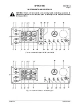
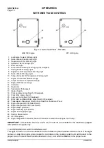
Fig. 4.4. Instrument Panel – RH Side
QSK 19C Engine
KT 19-C Engine
1. Low Engine Coolant Warning Light
2. Service Brake Filter Warning Light
3. Transmission Filter Warning Light.
4. Hydraulic Filter Warning Light.
5. Fuel Level Light.
6. Ground Driven Steering Warning Light (If Equipped)
7. Parking Brake Warning Light.
8. Engine Coolant Temperature Warning Light
9. Service Brake Warning Light.
10. Torque Converter Oil Temperature Warning Light.
11. Engine Coolant Temperature Gauge.
12. Torque Converter Temperature Gauge.
13. Engine Oil Pressure Gauge.
14. Voltmeter.
15. Hourmeter.
16. Tachometer (If Equipped).
17. Ignition Switch.
18. Front Auxiliary Lamps Switch (If Equipped).
19. Front Work Lamps Switch.
20. Low Level Lamp Switch (if Equipped).
21. Ether Start and Rear Work Lamps Switch (If Equipped).
22. Transmission Disconnect / Bulb Check Switch on Instrument Panel
23. Engine Diagnostic ECM Select Switch.
24. Engine Diagnostic ECM Check Switch.
25. Engine Stop Light (Red).
26. Engine Warning Light (Yellow).
27. Engine Fluid Light (Orange).
28. Parking Brake Switch
29. 24 V Receptacle
30. Engine Diagnostic Connector (Second Connector Located Above Engine Fuel Pump)
IMPORTANT
: Components No’s 23, 24,25, 26, 27 and 30 are included in the machine equipped
with QSK-19-C engine only.
1. LOW ENGINE COOLANT WARNING LIGHT
This light will come on if the coolant level in the radiator top tank reaches minimum level. If this light
comes on, stop the engine, allow coolant to cool down in the cooling system and add coolant to the
proper level or correct leaks found beforehand, if any, and refill the radiator to the proper level.
Summary of Contents for 560C
Page 1: ...OM560C99 1E OPERATOR S MANUAL 560C SERIAL NUMBERS 15001 AND UP ...
Page 3: ......
Page 5: ......
Page 7: ......
Page 10: ...SECTION 1 INTRODUCTION ...
Page 12: ......
Page 16: ...SECTION 2 SAFETY PRECAUTIONS ...
Page 18: ......
Page 32: ...SECTION 3 MACHINE TRANSPORT AND STORAGE ...
Page 34: ......
Page 42: ...SECTION 4 OPERATING ...
Page 43: ......
Page 45: ......
Page 49: ...SECTION 4 OPERATING Page 6 OM560C99 1E DRESSTA UNIVERSAL SYMBOLS FOR INSTRUMENTS AND CONTROLS ...
Page 88: ...SECTION 5 MAINTENANCE ...
Page 141: ...SECTION 6 SPECIFICATIONS ...
Page 143: ......

