SECTION 5
MAINTENANCE
Page 32
OM560C99/1E
DRESSTA
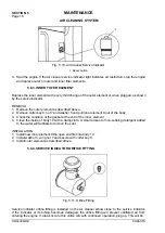
DRIVE AXLES
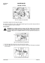
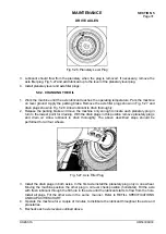
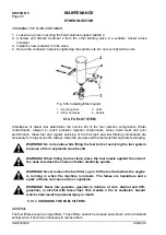
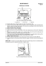
Fig. 5.28. Axle Oil Drain Plug
5.10. ELECTRICAL SYSTEM
5.10.1. ELECTRIC WIRES
WARNING! Before working on the electrical system, disconnect the electrical
system master switch and remove the key.
All terminals must be clean and fastened securely. Repair or replace all broken wires immediately.
Surface under all terminals must be clean and good electrical connections must be established
after reassembly. Also all clips must grip cables tightly to prevent vibrations and rapid cable wear.
All clips a straps must be closed in a workmanlike manner, so as not to damage the insulation.
5.10.2. CIRCUIT BREAKERS
Electrical circuits are protected by automatic reset circuit breakers. Electrical system is protected
with circuit breakers:
10 amp (2 units), 20 amp (1 unit), 25 amp (1 unit) and 30 amp (1 unit). In the event of a "short
circuit" or "ground", the circuit breaker will open before damage occurs and will continue to open
and close until the trouble clears or is corrected. When replacing use circuit breakers of the same
amps.
To replace circuit breaker carry out as follows:
1. Remove the screws mounting the instrument panel, lift the instrument panel and shift to the
side.
2. Remove the screws mounting the circuit breaker and replace it.
3. Reassembly in the reverse order.
5.10.3. BULB OR LAMP REPLACEMENT
GAUGE CLUSTER BULBS
For a bulb replacement carry out as follows:
1. Remove the screws mounting the gauge cluster to the instrument panel
2. Lift and shift the gauge cluster to the side.
3. Remove the socket, remove the burnt bulb install a new bulb and press in the socket home.
4. Re-install gauge cluster.
Summary of Contents for 560C
Page 1: ...OM560C99 1E OPERATOR S MANUAL 560C SERIAL NUMBERS 15001 AND UP ...
Page 3: ......
Page 5: ......
Page 7: ......
Page 10: ...SECTION 1 INTRODUCTION ...
Page 12: ......
Page 16: ...SECTION 2 SAFETY PRECAUTIONS ...
Page 18: ......
Page 32: ...SECTION 3 MACHINE TRANSPORT AND STORAGE ...
Page 34: ......
Page 42: ...SECTION 4 OPERATING ...
Page 43: ......
Page 45: ......
Page 49: ...SECTION 4 OPERATING Page 6 OM560C99 1E DRESSTA UNIVERSAL SYMBOLS FOR INSTRUMENTS AND CONTROLS ...
Page 88: ...SECTION 5 MAINTENANCE ...
Page 141: ...SECTION 6 SPECIFICATIONS ...
Page 143: ......

