


MAINTENANCE
SECTION 5
Page 45
DRESSTA
OM560C99/1E
HYDRAULIC SYSTEM
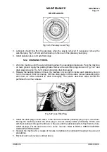
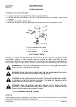
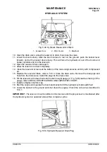
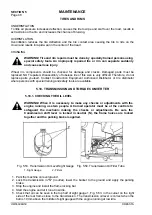
Fig. 5.49. Hydraulic Reservoir Oil Filters
1 - Access Door 2 - Filter Covers 3 - Breathers
10. Open the drain valve , allow the reservoir to drain, then close the valve.
11. Lower the boom slowly. After the boom comes to rest on the ground, push the bucket lever
forward, and let the bucket down slowly. This will force the hydraulic oil out of the boom and
bucket cylinders and into the reservoir.
12. Open the reservoir drain valve again.
13. Allow the reservoir to drain completely.
14. Clean the reservoir screens at the bottom of the tank using kerosene and dry with compressed
air.
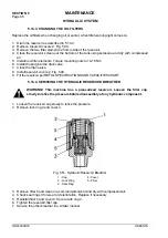
15. Replace the reservoir filters, refer to 5.14.3. Close the drain valve. Remove the drain pipe and
hose from the drain valve. Install the plug into the drain valve.
16. Fill the reservoir with clean fluid until the ball in sight gauge (2, Fig. 5.48) reaches the top of the
gauge, refer to REFILL SPECIFICATIONS AND CAPACITIES CHART.
17. Install and tighten the filler cap.
18. Start the engine and operate the boom and bucket to fill the hydraulic cylinders with fluid.
19. Lower the bucket to the ground and shut down the engine. Check the oil level as described in
5.14.1.
IMPORTANT:
The reservoir must be refilled in this manner until the proper level is maintained after
the hydraulic system is operated at least five complete cycles.
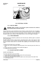
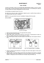
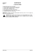
Fig. 5.50. Hydraulic Reservoir Drain Plug
Summary of Contents for 560C
Page 1: ...OM560C99 1E OPERATOR S MANUAL 560C SERIAL NUMBERS 15001 AND UP ...
Page 3: ......
Page 5: ......
Page 7: ......
Page 10: ...SECTION 1 INTRODUCTION ...
Page 12: ......
Page 16: ...SECTION 2 SAFETY PRECAUTIONS ...
Page 18: ......
Page 32: ...SECTION 3 MACHINE TRANSPORT AND STORAGE ...
Page 34: ......
Page 42: ...SECTION 4 OPERATING ...
Page 43: ......
Page 45: ......
Page 49: ...SECTION 4 OPERATING Page 6 OM560C99 1E DRESSTA UNIVERSAL SYMBOLS FOR INSTRUMENTS AND CONTROLS ...
Page 88: ...SECTION 5 MAINTENANCE ...
Page 141: ...SECTION 6 SPECIFICATIONS ...
Page 143: ......


