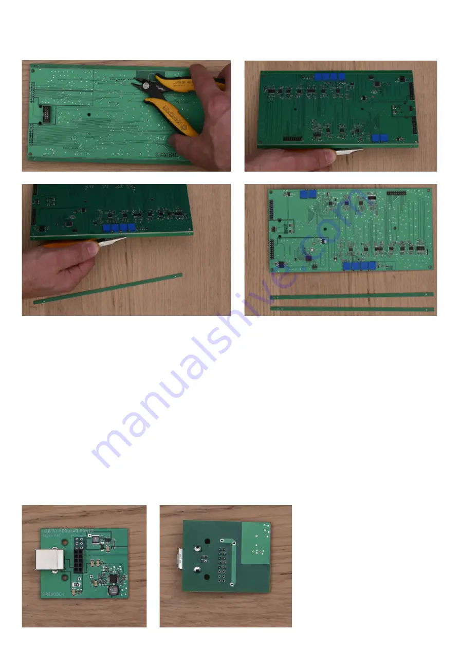
Then, cut the excess wires from the pre-assembled trimmers and remove the extra PCB from
the top and bottom side of the board.
1.5 Preparation of the power board
5
For this step you will need:
- The 0.7 solder wire + a soldering iron
- The USB jack
- The 10pin female header
Solder the USB jack and the header, as shown in the pictures.
You can also use this board as a generic modular power supply. Max supplied current is
200mA@+12V and 80mA@-12V. In order to do this, you need to solder a 16pin male
ribbon header
(not included in the kit)
, instead of the 10pin female.
Pin "1" is marked with a small circle at the bottom right.


